Oxygen Sensors Operation & Testing
Oxygen Sensors Operation & Testing. Stoichiometry. Stoichiometry. Stoichiometry in automotive terms is the principle that refers to the “ideal” air to fuel ratio being consumed in the cylinder.


Oxygen Sensors Operation & Testing
E N D
Presentation Transcript
Oxygen Sensors Operation & Testing
Stoichiometry Stoichiometry in automotive terms is the principle that refers to the “ideal” air to fuel ratio being consumed in the cylinder. At 14.7 pound of air to 1 pound of fuel, even pre-converter HC, CO and NOX exhaust gases will be at their lowest levels. However, no vehicle can maintain a precise 14.7:1 mixture.
Stoichiometry Constant changes in the throttle position, engine load, and vehicle speed cause the mixture to vary almost constantly. The feedback system has to adjust the mixture constantly to keep the mixture near optimum levels. The system keeps the air/fuel mixture close to the ideal by constantly switching back and forth on either side of stoichiometry.
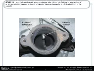
Stoichiometry The engine management system is responsible for maintaining stoichiometry allowing the catalytic converter to operate at maximum efficiency while maintaining minimal emissions. The engine management system uses an oxygen sensor in the exhaust to determine if the air/fuel mixture is rich or lean and adjusts to compensate.
Oxygen Sensor Operation
Oxygen Sensor Operation The oxygen sensor plays a critical role in providing optimum engine performance with minimal emissions. There are three basic types of oxygen sensors. They are the: • Zirconia • Titania • Air Fuel
Oxygen Sensor Operation - Zirconia The Zirconia oxygen sensor produces a voltage by distributing oxygen ions across the surface of the two platinum electrodes.
Oxygen Sensor Operation - Zirconia An ion is an electrically charged atom. Oxygen ions have a negative charge and are attracted to the ZrO2 electrolyte. Since the inside of the thimble-shaped electrolyte is exposed to a much higher concentration of oxygen ions than its outer side (exhaust side), a potential difference is created between the two platinum electrodes.
Oxygen Sensor Operation - Zirconia The platinum is used as an electrical connection point. It also serves as a catalyst for the chemical reaction that enables the sensor to produce a voltage. It needs about 599°F (315°C) to completely set up the catalytic reaction of the ZrO2 electrolyte. At temperatures below 572°F (300°C), the difference between rich and lean voltages diminishes rapidly. This is the reason the computer ignores the oxygensensor signal until proper operating temperature is achieved.
Oxygen Sensor Operation - Zirconia A properly functioning zirconia oxygen sensor generates a voltage up to one volt depending on the oxygen content in the exhaust gas. When the air/fuel ratio is lean, the oxygen content in the exhaust gas is high. This will cause the oxygen sensor to produce voltage less than 300 millivolts. Conversely, there is less residual oxygen in the exhaust gas when the mixture is rich. Under this condition, the oxygen sensor will output a voltage in excess of 600 millivolts.
Oxygen Sensor Operation - Zirconia
Oxygen Sensor Operation - Titania Many Titania sensors act similar to the Zirconia sensor. The sensor uses a thick film of Titania at the tip of the element to detect oxygen concentrations in the exhaust gas. They have less than one volt when rich and close to five volts when lean. Titania sensors are typically used on vehicles that are likely to be driven off-road, because they do not require a fresh air vent that can become clogged with debris.
Oxygen Sensor Operation - Titania Some Titania oxygen sensors, as used on the Toyota Corolla GTS (except California) - and the V-6, 2WD California truck, operate differently in that they have close to one volt when lean and close to zero volts when rich.
Oxygen Sensor Operation - Air Fuel (AF) The AF sensor, also called a broadband planar sensor or Lean Air Fuel sensor (LAF), used in some applications resembles the heated Zirconia sensor in appearance only. The AF sensor improves overall efficiency by keeping the fuel control system in closed-loop during a much wider range of driving conditions. Subsequently, instead of using preprogrammed, open loop air/fuel ratios in many situations, the PCM fine-tunes the mixture much more closely based on the actual oxygen readings from the exhaust.
Oxygen Sensor Operation - Air Fuel (AF) AF sensors may be configured as seven-wire, five wire, or four-wire sensors.
Oxygen Sensor Operation - Air Fuel (AF) AF sensors are used as the pre-catalyst (upstream) oxygen sensors. On a four-wire AF sensor, two wires are power and ground for the sensor heater, and the other two wires are used for the exhaust mixture signal.
Oxygen Sensor Operation - Air Fuel (AF) The Air Fuel oxygen sensor heater is designed to heat the oxygen sensor thimble to a minimum of 1200°F. This temperature is double that of an early four-wire sensor and is required for the AF sensor to properly sample the exhaust oxygen content. When the AF sensor heater is commanded on by the PCM, approximately 8 amps of current should be flowing through the circuit.
Oxygen Sensor Operation - Air Fuel (AF) The PCM controls the voltage to a fixed voltage. It is difficult to confirm the AF sensor voltage without a scan tool as the voltages at the terminals are fixed and any change is noted within the PCM itself. The voltage signal is proportional to the change in the air/fuel mixture. This allows the PCM to more accurately judge the exact air/fuel ratio under a wide variety of conditions and quickly adjust the amount of injector pulse. Think of the AF sensor as a generator that is capable of changing polarity.
Oxygen Sensor Operation - Air Fuel (AF) The AF sensor has two zirconia elements that share a diffusion chamber. The AF sensor is really two O2 sensors in one unit. There are three chambers in the AF sensor: • The first chamber contacts the exhaust flow. • The diffusion chamber between the elements. • The air reference chamber.
Oxygen Sensor Operation - Air Fuel (AF)
Oxygen Sensor Operation - Air Fuel (AF) The first chamber is really the outside of the sensor, which contacts the exhaust. The diffusion chamber is the area between the two zirconia elements and the air reference chamber is at the other end. The basic operating principle behind the AF sensor is that by controlling the amount of O2 in the diffusion chamber, you can control its operating range. One of the zirconia elements acts as an oxygen pump. We discussed how a flow of oxygen ions creates a flow of electrons. The inverse is also true. A flow of electrons applied to the sensor causes a flow of ions. This is what happens when you charge a car battery.
Oxygen Sensor Operation - Air Fuel (AF) Notice how the elements are wired in parallel, and there is a common ground lead. This ground is a reference point for the ECM. Do not confuse it with the vehicle ground. In fact, if you measure the voltage between the sensor ground and the vehicle ground, you will see about 2.7 volts.
Oxygen Sensor Operation - Air Fuel (AF) For this explanation, we will distinguish the two zirconia elements by calling one, sensor #1 and the other, sensor #2. The ECM monitors the voltage between sensor #1 input and the ground lead. The ECM tries to hold the voltage difference between sensor #1 and the ground lead to 450 mV.
Oxygen Sensor Operation - Air Fuel (AF)
Oxygen Sensor Operation - Air Fuel (AF) When the mixture goes rich, oxygen ions flow from the diffusion chamber to the exhaust. The voltage on sensor #1 input increases. The ECM detects the voltage increase and reduces the voltage on sensor #2 input.
Oxygen Sensor Operation - Air Fuel (AF) The voltage on sensor #2 input then goes more negative than the ground voltage. This causes sensor #2 to pump oxygen out of the diffusion chamber into the air reference chamber. When the oxygen content of the diffusion chamber drops, the voltage on sensor #1 drops. At the same time that the ECM reduces the voltage on sensor #2 input, it is also reducing fuel delivery.
Oxygen Sensor Operation - Air Fuel (AF) When the mixture goes lean, oxygen ions flow from the exhaust into the diffusion chamber. The voltage on sensor #1 input decreases. The ECM detects the voltage decrease and increases the voltage on sensor #2 input. The voltage on sensor #2 input goes more positive than the ground voltage. This causes sensor #2 to pump oxygen into the diffusion chamber from the air reference chamber. The voltage between sensor #1 input and ground is consistently held at 450 mV.
Oxygen Sensor Operation - Air Fuel (AF) The ECM knows how rich or lean the exhaust is by how much amperage it takes the sensor #2 input to hold sensor #1 input voltage to 450 mV. • Positive voltage the mixture is lean. • Negative voltage the mixture is rich.
Oxygen Sensor Operation - Air Fuel (AF) Lean Mixture Zero Volts Rich Mixture
Oxygen Sensor Heater
Oxygen Sensor Heater To keep the engine operating in closed loop, an oxygen sensor must be maintained at a minimum temperature of approximately 572°F (300°C). To help maintain this temperature, the oxygen sensors used on OBD-II systems contain heating elements. These elements combined with exhaust gas temperature keep the oxygen sensor temperature at nearly 1200°F.
Oxygen Sensor Heater The PCM monitors the operation of the internal oxygen sensor-heating element. If the heater current exceeds approximately 2 amps (standard system) or 8 amps (AF system), the PCM will store a pending code and enter freeze frame data. Two consecutive failures of the Oxygen Sensor Heater Monitor will result in: • A matured DTC • MIL illumination
Diagnosis of Oxygen Sensor Aging
Oxygen Sensor Aging Age, contamination, and extreme heat can affect the oxygen sensor response characteristics. Degradation of the signal can be in the form of an extended response time (period duration) or a shift in the sensor voltage curve (sensor shift biased). Both conditions reduce the oxygen window, thereby reducing the catalyst capacity for exhaust gas conversion.
Oxygen Sensor Aging To find out if the computer is "in control" of a vehicle's air/fuel mixture, you need to view the oxygen sensor signal and determine the computer command. Digital Storage Oscilloscope (DSO) analysis will let you quickly determine whether the oxygen sensor is good and whether the feedback computer system is in control.
Determining System Control & Condition
Determining System Control Signature Balance analysis is a term that describes the appearance of the oxygen sensor waveform, and what that waveform says about the vehicle's running condition. Most technicians already know the oxygen sensor indicates engine mixture; what many technicians do not know is the oxygen sensor signal can show the overall condition of the engine.
Determining System Control In general, the oxygen sensor waveform should appear like the waveform in the graphic to be shown. They must switch continuously above and below 450 millivolts, switching between once every two seconds, and five times per second. In addition, it should not drop below zero volts, except from occasional noise. However, the AF sensor is an exception to this rule.
Determining System Control Remember: It is this switching from rich to lean and back again that sets up the conditions in the exhaust for a three-way catalytic converter to oxidize HC and CO and reduce NOX emissions efficiently.
Determining System Control Zero Volts
Determining System Control If the engine is not running right, the sensor will not develop a good waveform. If the oxygen sensor is damaged, the engine will not run right. So how can you tell whether the oxygen sensor waveform is not right because of a bad sensor or an engine problem?
Determining System Control By verifying the oxygen sensor - forcing the system full rich and full lean - you can check the maximum and minimum voltage levels the sensor produces, and how quickly it switches. Slow switch rates from a deteriorated O2 sensor causes poor performance and excessive exhaust emissions. In some cases, the engine may run fine but the vehicle will still fail an enhanced emissions test.
Verifying Zirconia Sensors