Download
1 / 18
230 likes | 769 Vues
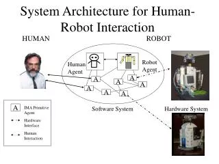
ROBOT SENSORS AND ROBOT VISON. T. Bajd and M. Mihelj. Robot sensors. Proprioceptive sensors position velocity joint torques Exteroceptive sensors force sensors tactile sensors proximity sensors distance sensors. Robot sensors. Electric sensors potentiometers strain gauges

E N D
ROBOT SENSORS AND ROBOT VISON T. Bajd and M. Mihelj
Robot sensors • Proprioceptive sensors • position • velocity • joint torques • Exteroceptive sensors • force sensors • tactile sensors • proximity sensors • distance sensors
Robot sensors • Electric sensors • potentiometers • strain gauges • Electromagnetic sensors • tachometer • Optical sensors • optical encoder
Reducer sensor reducer Using a reducer we decrease the joint angular velocity by factor with respect to the angular velocity of the motor. In the same time the joint torque is increased by the same factor.
Sensor of movement before transducer Sensor measurement error is reduced by factor . Sensors with larger range of motion are used.
Sensor of movement behind reducer Sensor measurement error directly enters the joint control loop. Sensors with smaller range of motion can be used.
Potentiometer The potentiometer represents a contact measuring method, because the wiper slides along the circular resistive winding.
Optical encoder The optical encoder is based on the transformation of the joint movement into a series of light pulses, which are further converted into electric pulses. It consists of a light source with lens, light detector (phototransistor or photodiode) and a rotating disk with slots.
Absolute encoder The absolute optical encoder measures the absolute angular position. The 16 logical states are represented by 4 bits. With 12 bits we can represent 4096 logical states resulting in 0.1° resolution. The absolute encoder determines also the direction of rotation.
Incremental encoder Incremental encoders supply the information about the changes in angular position. Measurement of joint displacement is based on counting the pulses from single track on the rotating disk. The second track determines the home position. The problem of determining the direction of rotation is solved by tangentially and radially displaced optical pairs on the first track.
Tachometer Tachometer is usually a direct current motor with permanent magnet. Its output voltage is proportional to the angular velocity of the rotor.
Force sensor Robot wrist sensor measures the forces and torques between robot end-point and environment. The strain gauges are attached to an elastic beam which is deformed under the stress caused by the applied force.
Force sensor The strain gauge behaves as a variable resistor whose resistance changes proportionally to its deformation. The small changes in the resistance are by the use of Wheatstone bridge converted into voltage signals.
The aim is to find the relation between a point in 2D image and the coordinates in 3D environment. A pinhole camera is hypothesized. A coordinate frame is attached to the camera (zc…optical axis, xc…rows, yc…columns of the image sensor). Robot vision – camera frame
Robot vision – image frame The origin of the image frame is placed in the intersection of the optical axis with the equivalent image plane. Scaling factor s = zc
Robot vision – index frame It is more convenient to use indices, marking the position of a pixel in a 2D image instead of metric units along the and axes of the image frame.
Robot vision – perspective matrix Thematrix represents the perspective projection from the camera frame into the corresponding index frame. In general the intrinsic parameters of the camera are not known.
Robot vision – calibration matrix The matrix represents the pose of the camera, i.e. the extrinsic parameters of the camera. The calibration matrix combines the intrinsic and extrinsic parameters of the camera which are determined in the calibration process.