Download

1 / 24
250 likes | 338 Vues
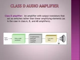
Class-D Audio Amplifier. System Description. Analog to PCM Conversion PCM to PWM Conversion. TMS 320F2808. Output Stage (Amplifier). Input Stage. Audio Source. Protection Circuit Buffer DC shift. Switching Amplifier H-Bridge LPF. The System. 12V Power Supply. Audio Source. 5V

E N D
System Description • Analog to PCM Conversion • PCM to PWM Conversion TMS 320F2808 Output Stage (Amplifier) Input Stage Audio Source • Protection Circuit • Buffer • DC shift • Switching Amplifier • H-Bridge • LPF
The System 12V Power Supply Audio Source 5V Power Supply
PCM to Duty Cycle Conversion PCM Value Duty Cycle Shift Right 2 bits
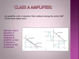
Input Circuit Functionality TMS 320F2808 ADC Input Stage Audio Source • Analog Signal • Amplitude Scaling • DC removal • Limits DSP Input Voltage 0 – 3.3 V • Protection Circuit • Buffer • DC shift • VRef for ADC • Analog to Digital (PCM) Conversion: • 0-3.3 V 0-0xFFF
Input Circuit DC Removal +Volume Buffer+HPF To eZDSP-F2808 P8-1 GND Reference Voltage 1.5 V Protection Circuit DC/DC Converter
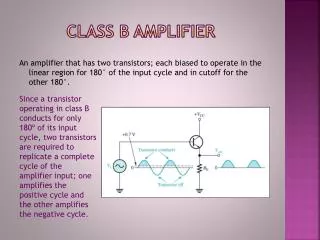
Output Circuit Functionality • PCM to PWM Conversion • PWM Control TMS 320F2808 CPU EPWM Output Stage (Amplifier) • Switching Amplifier • H-Bridge • LPF
Output Circuit PWM Inversion Drivers Protection Full Bridge LPF EPWM1 - P8/9 EPWM2 - P8/11
Voltage Supply 5 V eZDSP-F2808 Input Stage Output Stage (Amplifier) 3.3 V DC/DC 12 V
Software Requirements The input Signal in range 0~3V The Conversion Sequence starts on SOC signal Conversion Sequence capture 8 times the same channel with configuration: ADC Clock = 12.5 MHz S/H width = 320ns Generates Interrupt at the end of each Conversion Sequence At the Start: Initialize: CPU clock to 100MHz GPIO for PWM output Interrupt Vector (PIE) Set up ADC, PWM Enable HRPWM calibration Select Interrupt on ADC EOS Perform Endless Loop of HRPWM calibration PWM width is 1000 CPU clocks = 10us = 100KHz Timer in Up-count mode Values loaded at the end of PWM duty cycle When Timer is zero PWM is inactive When Timer = Value PWM is active Generate SOC signal at the start of each PWM duty cycle (Timer is zero) TMS 320F2808 ADC CPU EPWM
Timing Diagram Timer=zero CMPA Updated Timer=CMPA PWM Timer PWM1A=Set PWM1A=Clear PWM1A Out PWM2A=Clear PWM2A=Set PWM2A Out Timer=zero SOC is generated Analog to PCM Conversion SOC Impulse ADC generates Interrupt End-of-Sequence PCM tp PWM Conversion CMPA Calculation Interrupt Exit Interrupt ISR exit CMPA updated
ePWM1 Settings (1) • Time-Base Settings: • PWM Frequency 97.6 KHz (100 MHz/1024) • with up-count mode timer
ePWM1 Settings (2) • Action-Qualifier: • PWM= ‘1’ for TBCTR=0 • PWM =‘0’ for TBCTR=CMPA • Counter-Compare: • Load new Value at the start of PWM duty cycle
ePWM1 Settings (3) • Event-Trigger: • Generate SOC to module A at the start of PWM duty cycle
ePWM2 Settings (1) • Time-Base Settings: • PWM Frequency 97.6 KHz (100 MHz/1024) • with up-count mode timer
ePWM2 Settings (2) • Action-Qualifier: • PWM= ‘0’ for TBCTR=0 • PWM =‘1’ for TBCTR=CMPA • Counter-Compare: • Load new Value at the start of PWM duty cycle
ePWM2 Settings (3) • Event-Trigger not activated