Download
1 / 11
110 likes | 224 Vues
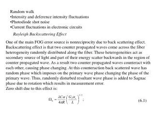
Random walk Intensity and deference intensity fluctuations Photodiode shot noise Current fluctuations in electronic circuits. Rayleigh Backscattering Effect. One of the main FOG error source is nonreciprocity due to back scattering effect.

E N D
Random walk • Intensity and deference intensity fluctuations • Photodiode shot noise • Current fluctuations in electronic circuits Rayleigh Backscattering Effect One of the main FOG error source is nonreciprocity due to back scattering effect. Backscattering effect is that two counter propagated waves come across the fiber heterogeneity randomly distributed along the fiber. These heterogeneities act as secondary source of light and part of their energy scatter backwards in the region of counter propagated wave. As a result two counter propagated waves counteract with each other, causing phase changing. At this counteraction back scattered wave has random phase which imposes on the primary wave phase changing the phase of the primary wave. Thus, randomly disturbed resultant wave phase is added to Sagnac phase due to rotation which results in measurement error. Zero shift due to this effect is: (6.1)
- beam entry angle into fiber core, Gs – along-fiber-guided scattering coefficient(1< Gs < 1.5), s – radiation attenuation coefficient for the account of backscattering. Estimation for the following parameters: = 10 m, R = 10 cm, = 6, s = 1.210-4 m-1, (0.5 дБ./км.), Gs = 1, L = 1000 м gives k 1700 deg/h. It is necessary to compensate for this error, because it is too high. Many techniques were proposed to reduce this error: signal integration to reduce fluctuation dispersion, wave power decreasing, phase or frequency modulation of the light etc. Widely used method to compensate for the error is backscattering wave phase randomization by applying short coherent light sources like luminescent or laser diode. Very good results can be obtained by using phase modulation technique for laser diode. Polarization Modulation Phase modulator usually used in FOG to increase sensitivity and/or to randomize phase counteraction of the counter propagated waves, causes polarization modulation. Polarization modulation leads to intensity modulation because any optical material intensity attenuation depends on direction of polarization. Intensity modulation for counter propagated waves, in its turn, leads to appearing
of phase deference, because of fiber refraction coefficient depends on wave intensity. • Besides, polarizer used in FOG is not ideal and has finite attenuation for orthogonal polarized beam. The ratio of orthogonal polarized beam intensity on the polarizer input to that on the output expressed in decibels (dB) is a measure of polarizer quality. Because of using non ideal polarizer, bias appears in FOG. This bias depends on environmental conditions, because attenuation ratio depends on the same factors and is proportional to square root of the attenuation ratio. • To reach FOG drift at the level of 0.01deg/h it is necessary to obtain the attenuation ratio less than 100 dB. • Polarization effect is significantly reduced by using polarization maintaining fiber. All modern FOGs use polarization maintaining fiber. Electrooptic Kerr Effect Nonlinear electrooptic effect is that refraction coefficient of the optical media depends on the beam intensity. Due to this effect there is an addition to the Sagnac phase when intensities of the counter propagated waves differ. The added angle rate k (bias) can be expressed as: (6.2)
Y 2Z air h n0 n1 q film d2 n2 substrate X Fig. 6.1. Channeling radiation by thin film. A – constant, Kd – beam intensity division coefficient in directional coupler, - time-average value of beam intensity. To reduce k we need Кd 0.5. The second way to reduce bias due to electro-optic effect is to choose light source so that - 2( )2 0. This is valid for luminescent and laser diodes. So, to reduce FOG bias due to backscattering and electro-optic Kerr effects it is necessary to use low coherence light sources. Integrated Optical Chip In order to create micro miniature and solid state FOG design, modern optical planar technologies are used. Hybrid FOG designs using integrated optical chip and fiber coil are now widely produced by many companies. In future, all components of the micro-optical gyro, including multiwinding optical contour will be • presented as one integrated optical chip. Physical basis for planar optical technology is the wave guiding property of thin dielectric materials, optically more density, than environmental medium. Such films are able to channel radiation. In simple waveguide structure air-film-substrate the relationship n0 < n2 < n1 , where n0, n1 , n2 – refraction coefficients of the (see fig.6.1).
Integrated optical PYP chip LD P Y Fiber coil PhD P Electronic unit Output Signal Fig.6.2. FOG using PYP chip. media and h= Zctg , where - radiation entry angle into medium, are accomplished to use total reflection effect. Radiation also propagates in the thin layers near the film increasing effective waveguide width. Waveguides located near each other counteract providing waveguide coupling. Such waveguides use to manufacture directional coupler, modulators and other planar optical components. Basic materials are for the film titanium (Ti), for substrate – LiNbO. Titanium is applied on the LiNbO substrate by using diffusion technology. Attenuation coefficient for Ti:LiNbO waveguide is less than 0.03 dB/cm. PYP Chip Manufacture After cutting and cleaning the LiNeO substrate plate, 0.05 m width titanium is evaporated in vacuum chamber, then it is processed by conventional lithographic technology and etched. Then 3–5 m width bands are deposited by using diffusion technology at temperature about 1000oC during 7 hours. Then, for example, aluminum film as electrodes is deposited by evaporation process and is processed by lithographic technology. In order to input and output beams the substrate but-ends are polished under the angle of 8 deg. to remove total reflection effect. FOG block diagram with PYP chip is depicted in fig.6.2.
Modern FOG parameters Table 6.1 shows FOG parameters of word leading manufacturers. All FOGs from these table use PYP chip. Table 6.1
3 2 4 1 Optical fiber manufacture technology The main and most critical component of fiber optic gyro is a coil with fiber optic cable wounded on it. Fiber cable consists of four envelopes (fig.4.9): 1. Core, diameter less than 10 m for single-mode fiber and more than 10 m for multi-mode one; 2. Cladding, dia. about 125 m; 3. Buffer, dia. about 250 m; and 4. Jacket, dia. about 400 m. The light is propagating along core only, the rest envelopes are auxiliary ones.When light is traveling in a dense medium hits a boundary at a steep angle (larger than the "critical angle" for the boundary, called full internal reflection angle), the light will be completely reflected. This effect is used in optical fibers to confine light in the core. Light travels along the fiber bouncing back and forth off of the boundary as is shown in fig.6.4. Because the light must strike the boundary with an angle greater than the critical angle, only light that enters the fiber within a certain range of angles can travel down Fig.6.3.The structure of a typical single-mode fiber. • 1. Core: 8 μm diameter; 2. Cladding: 125 μm dia.3. Buffer: 250 μm dia.4. Jacket: 400 μm dia. Fig.6.4. Pricipal of light waveguiding
the fiber without leaking out. This range of angles is called the acceptance cone of the fiber. The size of this acceptance cone is a function of the refractive index difference between the fiber's core and cladding. In simpler terms, there is a maximum angle from the fiber axis at which light may enter the fiber so that it will propagate, or travel, in the core of the fiber. The sine of this maximum angle is the numerical aperture (NA) of the fiber. Fiber with a larger NA requires less precision to splice and work with than fiber with a smaller NA. Single-mode fiber has a small NA.In single-mode fibers, a significant fraction of the energy in the bound mode travels in the cladding. The most common type of single-mode fiber has a core diameter of 8–10 micrometers and is designed for use in the near infrared. The mode structure depends on the wavelength of the light used, so that this fiber actually supports a small number of additional modes at visible wavelengths. Multi-mode fiber, by comparison, is manufactured with core diameters as small as 50 micrometers and as large as hundreds of micrometers. Opticalglass fibers are almost always made from silica. Silica exhibits fairly good optical transmission over a wide range of wavelengths. In the near-infrared (near IR) portion of the spectrum, particularly around 1.5 μm, silica can have extremely low absorption and scattering losses of the order of 0.2 dB/km.
Fiber manufacturing process • Standard optical fibers are made by constructing a large-diameter "preform", with a carefully controlled refractive index profile, and then "pulling" the preform to form the long, thin optical fiber. The preform is commonly made by three chemical vapor deposition methods: inside vapor deposition, outside vapor deposition, and axial vapor deposition. With inside vapor deposition, the perform starts as a hollow glass tube approximately 40 centimeters long, which is placed horizontally and rotated slowly on a lathe.Gases such as silicon tetrachloride (SiCl4) or germanium tetrachloride (GeCl4) are injected with oxygen in the end of the tube. Fig.6.5. • The gases are then heated by means of an external hydrogen burner, bringing the temperature of the gas up to 1600°C, where the tetrachloride reacts with oxygen to produce silica dioxide (SiO2) or germanium dioxide (GeO2) particles (see fig.6.5).
When the reaction conditions are chosen to allow this reaction to occur in the gas phase throughout the tube volume, this technique is called modified chemical vapor deposition (MCVD).The oxide particles then agglomerate to form large particle chains, which subsequently deposit on the walls of the tube as soot. The deposition is due to the large difference in temperature between the gas core and the wall causing the gas to push the particles outwards (this is known as thermophoresis). The torch is then traversed up and down the length of the tube to deposit the material evenly. After the torch has reached the end of the tube, it is then brought back to the beginning of the tube and the deposited particles are melted to form a solid layer. This process is repeated until a sufficient amount of material has been deposited. For each layer the composition can be modified by varying the gas composition, resulting in precise control of the finished fiber's optical properties.In outside vapor deposition or vapor axial deposition, the glass is formed by flame hydrolysis, a reaction in which silicon tetrachloride and germanium tetrachloride are oxidized by reaction with water (H2O) in an oxyhydrogen flame. In outside vapor deposition the glass is deposited onto a solid rod, which is removed before further processing. In vapor axial deposition, a short seed rod is used, and a porous preform, whose length is not limited by the size of the source rod, is built up on its end. The porous preform is consolidated into a transparent, solid preform by heating to about 1500°C.
Most modern fiber optic gyros use polarization maintaining fiber the core of which has no round geometry. However, single-mode fiber is also used in less accurate and lower cost gyros.