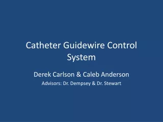
Catheter Guidewire Control System
Catheter Guidewire Control System. Derek Carlson & Caleb Anderson Advisors: Dr. Dempsey & Dr. Stewart. Contents. Caleb Anderson Overview of Catheterization Project Summary Overall Block Diagram Electroactive Polymer Polymer data Platinum vs. Gold Microcontroller Development board

Catheter Guidewire Control System
E N D
Presentation Transcript
Catheter Guidewire Control System Derek Carlson & Caleb Anderson Advisors: Dr. Dempsey & Dr. Stewart
Contents • Caleb Anderson • Overview of Catheterization • Project Summary • Overall Block Diagram • Electroactive Polymer • Polymer data • Platinum vs. Gold • Microcontroller Development board • Derek Carlson • Amplifier Circuit • Motor Controller Board • Stepper Motors • MATLAB progress • Final Equipment List • Schedule • Collaborative Progress w/ ME’s • Conclusions • Questions?
Currently requires the use of multiple guidewires Guidewire allows easy travel to area of blockage Catheter slides directly over guidewire Guidewire is then removed from vessel Overview of Catheterization www.forsythradiology.com www.amplatzer.com
Project Summary • Eliminate the need for different guidewires • Add precision control to the guidewire itself. • Add remote control to the guidewire simply by viewing the patient through a camera. • Control is implemented using a joystick interfaced with Matlab. • A purchased controller board runs two stepper motors. • These stepper motors will be used for lateral motion and guidewire advancement. • A voltage reactive polymer will be used for precision tip control.
Electroactive Polymer • Material purchased from Environmental Robots, Inc by the Mechanical Engineering department • Responds to a DC voltage between -5V to 5V • +-5V results in an approximate 90 degree bend • Tip will be made of this material for precision control
Electroactive Polymer Characteristics • 2 kinds of polymer available • Platinum plated • Gold plated • We discussed testing procedures with the ME’s. • They returned voltage vs. curvature data for both types of polymer • Results
Polymer Run Times Platinum Plated Gold Plated
Platinum vs. Gold • Discussed results with ME students • Linearity issues • Runtime • Current Draw • Gold polymer was decided upon • Runtime was the largest reason • Slightly more linear as well • Did not have quite as large of an angle of deflection
Polymer Characteristic Problems • Polymer behavior is not uniform • Polymer to polymer • Multiple runs – same polymer • Voltage response – highly nonlinear • Earlier results? • DC voltage only test signal of value • Other test signals?
80535 Microcontroller Development Board • D/A used to create 0 to 5 volt test signal • 2 methods of input • Keypad • Joystick • 0-100 % Entry • LCD Readout
Contents • Caleb Anderson • Overview of Catheterization • Project Summary • Overall Block Diagram • Electroactive Polymer • Polymer data • Platinum vs. Gold • Microcontroller Development board • Derek Carlson • Amplifier Circuit • Motor Controller Board • Stepper Motors • MATLAB progress • Final Equipment List • Schedule • Collaborative Progress w/ ME’s • Conclusions • Questions?
Amplifier Circuit • Frequency Response 20 Hz – 20 kHz • Minimum Gain of 10 for no oscillation • Non-inverting so unity at DC • Mute needs 0.5 mA
Motor Controller Board • Runs off of a USB-Serial driver • Dual supply mode • 2 motors connected draw roughly 1 amp when running • Controlled via MATLAB’s serial communication tools
Stepper Motors • Used for rotation and advancement of guidewire • (2) Jameco 8.4 V motors ordered • Suggested in Motor Controller Board documentation • Tested with Motor Controller board • Full functionality achieved • Total current draw = roughly 1 amp while running.
MATLAB progress • Serial control of board completed in command-line form • Able to move motors independently • Can move motors a certain distance, and then have them return • All commands documented in BiStep controller board tested and functional
MATLAB GUI progress • Basic GUI designed • Layout including buttons for advancement and retraction of guidewire • Command line interface for testing • Webcam function via command buttons • Webcam is functional separately, has not been implemented into GUI at this point
Final Equipment List • (2) 1 degree stepper motors • (1) Bistep Motor Controller Board • (1) Electroactive polymer tip • (1) Surgical Guidewire • (3) DC voltage sources – (2) for motor control (1) for op-amp. • (1) PC USB Webcam • (1) Logitech Wingman Pro Attack 2 Joystick • TBA – mechanical system to test guidewire
Completion of Schedule • Weeks 1-3 • Stepper motor MATLAB interface (Derek & Caleb) • Webcam MATLAB interface (Caleb) • RS-232 MATLAB interface (Derek) • Weeks 4-6 • GUI for user input (Both) • Develop polymer electrical characteristics (Both) • Detailed current draw calculations • Weeks 7-8 • Develop power electronics to actuate polymer (Derek) • Possible polymer shielding concerns (Caleb) • Weeks 9-10 • Stepper motor physical interface (Caleb) • Guidewire drive system (propulsion, rotation, etc.) (Derek) • Weeks 11-14 • Build test system (Both) • Finalize report & Presentation(Both)
Collaborative Progress • Several meeting have been held with ME’s • Shielding concerns have been discussed • Medical grade wire for supply of power • Electrically conductive adhesive for connecting polymer to wire • Test system construction • ME’s focused on prototype guidewire • Our focus was on control system
Conclusions • Electroactive polymers very promising for use in the medical field • Gold plated polymer used for guidewire tip control is not developed enough for use • Material is unpredictable and inconsistent • Further research and development necessary to generate more useful polymer • Other polymers may exist that would respond better