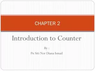
Timer/counter Chapter 12
Timer/counter Chapter 12. A counter register. A simple design (counting people) First design . Sensor. A simple design (counting people) Second design. Sensor. A simple design (making delay). A generic timer/counter. Delay generating Counting Wave-form generating Capturing.

Timer/counter Chapter 12
E N D
Presentation Transcript
A generic timer/counter • Delay generating • Counting • Wave-form generating • Capturing
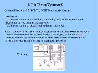
Timers in AVR • 1 to 6 timers • 3 timers in ATmega32 • 8-bit and 16-bit timers • two 8-bit timers and one 16-bit timer in ATmega32
Timer in AVR • TCNTn (Timer/Counter register) • TOVn(Timer Overflow flag) • TCCRn(Timer Counter control register) • OCRn(output compare register) • OCFn(output compare match flag) TCCRn TCNTn TOVn = OCFn Comment: All of the timer registers are byte-addressable I/O registers OCRn
Timer 0 TCCR0 TCNT0 TOV0 = OCF0 OCR0
Timer Mode (WGM) WGM00 WGM01 Comment 0 0 Normal 0 1 CTC (Clear Timer on Compare Match) 1 0 PWM, phase correct 1 1 Fast PWM Clock Selector (CS) CS02 CS01 CS00Comment 0 0 0 No clock source (Timer/Counter stopped) 0 0 1 clk (No Prescaling) 0 1 0 clk / 8 0 1 1 clk / 64 1 0 0 clk / 256 1 0 1 clk / 1024 1 1 0 External clock source on T0 pin. Clock on falling edge 1 1 1 External clock source on T0 pin. Clock on rising edge
TOV TOV TOV Normal mode TCNT0 0xFF time 0 FF 1 0 FE TOV0: 2 1 0 TOV0 = 1
Example 1: Write a program that waits 14 machine cycles in Normal mode. $100 -$0E $F2 WGM00 WGM01 Comment 0 0 Normal 0 1 CTC 1 0 PWM, phase correct 1 1 Fast PWM 14 = $0E $F2 0 0 1 0 0
Example 1: write a program that waits 14 machine cycles in Normal mode. $100 -$0E $F2 .INCLUDE "M32DEF.INC" LDI R16,0x20 SBI DDRB,5 ;PB5 as an output LDI R17,0 OUT PORTB,R17 BEGIN: LDI R20,0xF2 OUT TCNT0,R20 ;load timer0 LDI R20,0x01 OUT TCCR0,R20 ;Timer0,Normal mode,int clk AGAIN: IN R20,TIFR ;read TIFR SBRS R20,0 ;if TOV0 is set skip next inst. RJMP AGAIN LDI R20,0x0 OUT TCCR0,R20 ;stop Timer0 LDI R20,(1<<TOV0) ;R20 = 0x01 OUT TIFR,R20 ;clear TOV0 flag EOR R17,R16 ;toggle D5 of R17 OUT PORTB,R17 ;toggle PB5 RJMP BEGIN DDRB = 1<<5; PORTB &= ~(1<<5); //PB5=0 while (1) { TCNT0 = 0xF2; TCCR0 = 0x01; while((TIFR&(1<<TOV0))==0); TCCR0 = 0; TIFR = (1<<TOV0); PORTB = PORTB^(1<<5); } Question: How to calculate the delay generated by the timer? Answer: 1) Calculate how much a machine clock lasts. T= 1/f 2) Calculate how many machine clocks it waits. 3) Delay = T * number of machine cycles
In example 1 calculate the delay. Imagine XTAL = 10 MHz. .INCLUDE "M32DEF.INC" LDI R16,0x20 SBI DDRB,5 ;PB5 as an output LDI R17,0 OUT PORTB,R17 BEGIN: LDI R20,0xF2 OUT TCNT0,R20 ;load timer0 LDI R20,0x01 OUT TCCR0,R20 ;Timer0,Normal mode,int clk AGAIN: IN R20,TIFR ;read TIFR SBRS R20,0 ;if TOV0 is set skip next inst. RJMP AGAIN LDI R20,0x0 OUT TCCR0,R20 ;stop Timer0 LDI R20,0x01 OUT TIFR,R20 ;clear TOV0 flag EOR R17,R16 ;toggle D5 of R17 OUT PORTB,R17 ;toggle PB5 RJMP BEGIN • Solution 1 (inaccurate): • 1) Calculating T: • T = 1/f = 1/10M = 0.1µs • Calculating num of machine cycles: • $100 • -$F2 • $0E = 14 • Calculating delay • 14 * 0.1µs = 1.4 0µs
Accurate calculating Other than timer, executing the instructions consumes time; so if we want to calculate the accurate delay a program causes we should add the delay caused by instructions to the delay caused by the timer LDI R16,0x20 SBI DDRB,5 LDI R17,0 OUT PORTB,R17 BEGIN: LDI R20,0xF2 1 OUT TCNT0,R20 1 LDI R20,0x01 1 OUT TCCR0,R20 1 AGAIN: IN R20,TIFR 1 SBRS R20,0 1 / 2 RJMP AGAIN 2 LDI R20,0x0 1 OUT TCCR0,R20 1 LDI R20,0x01 1 OUT TIFR,R20 1 EOR R17,R16 1 OUT PORTB,R17 1 RJMP BEGIN 2 18 Delay caused by timer = 14 * 0.1µs = 1.4 µs Delay caused by instructions = 18 * 0.1µs = 1.8 Total delay = 3.2 µs wave period = 2*3.2 µs = 6.4 µs wave frequency = 156.25 KHz
Finding values to be loaded into the timer • Calculate the period of clock source. • Period = 1 / Frequency • E.g. For XTAL = 8 MHz T = 1/8MHz • Divide the desired time delay by period of clock. • Perform 256 - n, where n is the decimal value we got in Step 2. • Set TCNT0 = 256 - n
Example 2: Assuming that XTAL = 10 MHz, write a program to generate a square wave with a period of 10 ms on pin PORTB.3. • For a square wave with T = 10 µs we must have a time delay of 5 µs. Because XTAL = 10 MHz, the counter counts up every 0.1 µs. This means that we need 5 µs / 0.1 µs = 50 clocks. 256 - 50 = 206. .INCLUDE "M32DEF.INC" LDI R16,0x08 SBI DDRB,3 ;PB3 as an output LDI R17,0 OUT PORTB,R17 BEGIN: LDI R20,206 OUT TCNT0,R20 ;load timer0 LDI R20,0x01 OUT TCCR0,R20 ;Timer0,Normal mode,int clk AGAIN: IN R20,TIFR ;read TIFR SBRS R20,TOV0 ;if TOV0 is set skip next RJMP AGAIN LDI R20,0x0 OUT TCCR0,R20 ;stop Timer0 LDI R20,0x01 OUT TIFR,R20 ;clear TOV0 flag EOR R17,R16 ;toggle D3 of R17 OUT PORTB,R17 ;toggle PB3 RJMP BEGIN DDRB = 1<<3; PORTB &= ~ (1<<3); while (1) { TCNT0 = 206; TCCR0 = 0x01; while((TIFR&0x01) == 0); TCCR0 = 0; TIFR = 1<<TOV0; PORTB = PORTB ^ (1<<3); }
Solution 1) Calculating T: T = 1/f = 1/10MHz = 0.1µs 2) Calculating delay 256 * 0.1µs = 25.6µs Example 3: Modify TCNT0 in Example 2 to get the largest time delay possible with no prescaler. Find the delay in µs. In your calculation, do not include the overhead due to instructions. • To get the largest delay we make TCNT0 zero. This will count up from 00 to 0xFF and then roll over to zero. .INCLUDE "M32DEF.INC" LDI R16,1<<3 SBI DDRB,3 ;PB3 as an output LDI R17,0 OUT PORTB,R17 BEGIN: LDI R20,0x0 OUT TCNT0,R20 ;load Timer0 LDI R20,0x01 OUT TCCR0,R20 ;Timer0,Normal mode,int clk AGAIN: IN R20,TIFR ;read TIFR SBRS R20,TOV0 ;if TOV0 is set skip next RJMP AGAIN LDI R20,0x0 OUT TCCR0,R20 ;stop Timer0 LDI R20,0x01 OUT TIFR,R20 ;clear TOV0 flag EOR R17,R16 ;toggle D3 of R17 OUT PORTB,R17 ;toggle PB3 RJMP BEGIN DDRB = 1 << 3; PORTB &= ~(1<<3); while (1) { TCNT0 = 0x0; TCCR0 = 0x01; while((TIFR&(1<<TOV0))==0); TCCR0 = 0; TIFR = 0x01; PORTB = PORTB^(1<<3); }
Generating Large Delays • Using loop • Prescaler • Bigger counters
OCF0 OCF0 OCF0 CTC (Clear Timer on Compare match) mode TCNT0 0xFF OCR0 time 0 OCR0 0 xx TOV0: 2 1 0 OCF0: 1 TOV0 = no change OCF0 = 1 0
Example 4: Rewrite example 2 using CTC Rewrite example 2 using CTC • For a square wave with T = 10 µs we must have a time delay of 5 µs. Because XTAL = 10 MHz, the counter counts up every 0.1 µs. This means that we need 5 µs / 0.1 µs = 50 clocks. Therefore, we have OCR0= 49. .INCLUDE "M32DEF.INC" LDI R16,0x08 SBI DDRB,3 ;PB3 as an output LDI R17,0 OUT PORTB,R17 LDI R20,49 OUT OCR0,R20 ;load timer0 BEGIN: LDI R20,0x09 OUT TCCR0,R20 ;Timer0,CTC mode,int clk AGAIN: IN R20,TIFR ;read TIFR SBRS R20,OCF0 ;if OCF0 is set skip next RJMP AGAIN LDI R20,0x0 OUT TCCR0,R20 ;stop Timer0 LDI R20,0x02 OUT TIFR,R20 ;clear TOV0 flag EOR R17,R16 ;toggle D3 of R17 OUT PORTB,R17 ;toggle PB3 RJMP BEGIN DDRB |= 1<<3; PORTB &= ~(1<<3); while (1) { OCR0 = 49; TCCR0 = 0x09; while((TIFR&(1<<OCF0))==0); TCCR0 = 0; //stop timer0 TIFR = 0x02; PORTB.3 = ~PORTB.3; }
Timer2 • Timer0 • Timer2 TCCR0 TCCR2 TCNT0 TCNT2 TOV0 TOV2 = OCF0 = OCF2 OCR0 OCR2
The difference between Timer0 and Timer2 • Timer0 • Timer2 CS02 CS01 CS00Comment 0 0 0 Timer/Counter stopped 0 0 1 clk (No Prescaling) 0 1 0 clk / 8 0 1 1 clk / 64 1 0 0 clk / 256 1 0 1 clk / 1024 1 1 0 External clock (falling edge) 1 1 1 External clock (rising edge) CS22 CS21 CS20Comment 0 0 0 Timer/Counter stopped 0 0 1 clk (No Prescaling) 0 1 0 clk / 8 0 1 1 clk / 32 1 0 0 clk / 64 1 0 1 clk / 128 1 1 0 clk / 256 1 1 1 clk / 1024
Timer 1 OCR1BH OCR1BL = OCF1B TCNT1H TCNT1L TCCR1A TCCR1B TOV1 = OCF1A OCR1AH OCR1AL
Clock Selector (CS) CS12 CS11 CS10Comment 0 0 0 No clock source (Timer/Counter stopped) 0 0 1 clk (No Prescaling) 0 1 0 clk / 8 0 1 1 clk / 64 1 0 0 clk / 256 1 0 1 clk / 1024 1 1 0 External clock source on T0 pin. Clock on falling edge 1 1 1 External clock source on T0 pin. Clock on rising edge
.INCLUDE "M32DEF.INC" LDI R16,HIGH(RAMEND) ;init stack pointer OUT SPH,R16 LDI R16,LOW(RAMEND) OUT SPL,R16 SBI DDRB,5 ;PB5 as an output BEGIN:SBI PORTB,5 ;PB5 = 1 RCALL DELAY_1ms CBI PORTB,5 ;PB5 = 0 RCALL DELAY_1ms RJMP BEGIN DELAY_1ms: LDI R20,0xD8 OUT TCNT1H,R20 ;TEMP = 0xD8 LDI R20,0xF0 OUT TCNT1L,R20 ;TCNT1L = 0xF0, TCNT1H = TEMP LDI R20,0x0 OUT TCCR1A,R20 ;WGM11:10=00 LDI R20,0x1 OUT TCCR1B,R20 ;WGM13:12=00,CS=CLK AGAIN:IN R20,TIFR ;read TIFR SBRS R20,TOV1 ;if OCF1A is set skip next instruction RJMP AGAIN LDI R20,1<<TOV1 OUT TIFR,R20 ;clear TOV1 flag LDI R19,0 OUT TCCR1B,R19 ;stop timer OUT TCCR1A,R19 ; RET TCNT1H TCNT1L LDI R20,HIGH(-10000) OUT TCNT1H,R20 LDI R20, ,LOW(-10000) OUT TCNT1L,R20 ;Timer1 overflows after 10000 machine cycles Assuming XTAL = 10 MHz write a program that toggles PB5 once per millisecond, using Normal mode. XTAL = 10 MHz 1/10 MHz = 0.1 µs Num. of machine cycles = 1 ms / 0.1 µs = 10,000 TCNT1 = 65,536 – 10,000 = 55,536 = $D8F0
TEMP register LDI R20,0xF3 OUT TCNT1H,R20 LDI R20,0x53 OUT TCNT1L,R20 IN R20,TCNT1L IN R21,TCNT1H a = TCNT1L; b = TCNT1H; TCNT1H = 0xF3; TCNT1L = 0x53;
Assuming XTAL = 10 MHz write a program that toggles PB5 once per millisecond, using CTC mode. .INCLUDE "M32DEF.INC" LDI R16,HIGH(RAMEND) OUT SPH,R16 LDI R16,LOW(RAMEND) OUT SPL,R16 SBI DDRB,5 ;PB5 as an output BEGIN:SBI PORTB,5 ;PB5 = 1 RCALL DELAY_1ms CBI PORTB,5 ;PB5 = 0 RCALL DELAY_1ms RJMP BEGIN DELAY_1ms: LDI R20,0x00 OUT TCNT1H,R20 ;TEMP = 0 OUT TCNT1L,R20 ;TCNT1L = 0, TCNT1H = TEMP LDI R20,0x27 OUT OCR1AH,R20 ;TEMP = 0x27 LDI R20,0x0F OUT OCR1AL,R20 ;OCR1AL = 0x0F, OCR1AH = TEMP LDI R20,0x3 OUT TCCR1A,R20 ;WGM11:10=11 LDI R20,0x19 OUT TCCR1B,R20 ;WGM13:12=11,CS=CLK AGAIN: IN R20,TIFR ;read TIFR SBRS R20,OCF1A ;if OCF1A is set skip next instruction RJMP AGAIN LDI R20,1<<OCF1A OUT TIFR,R20 ;clear OCF1A flag LDI R19,0 OUT TCCR1B,R19 ;stop timer OUT TCCR1A,R19 ; RET
Counting T0 6 7
Example Assuming that clock pulses are fed into pin T0, write a program for counter 0 in normal mode to count the pulses on falling edge and display the state of the TCNT0 count on PORTC. .INCLUDE "M32DEF.INC" CBI DDRB,0 ;make T0 (PB0) input LDI R20,0xFF OUT DDRC,R20 ;make PORTC output LDI R20,0x06 OUT TCCR0,R20 ;counter, falling edge AGAIN: IN R20,TCNT0 OUT PORTC,R20 ;PORTC = TCNT0 IN R16,TIFR SBRS R16,TOV0 RJMP AGAIN ;keep doing it LDI R16,1<<TOV0 OUT TIFR, R16 RJMP AGAIN ;keep doing it
Assuming that clock pulses are fed into pin T1. Write a program for counter 1 in CTC mode to make PORTC.0 high every 100 pulses. .INCLUDE "M32DEF.INC" CBI DDRB,1 ;make T1 (PB1) input SBI DDRC,0 ;PC0 as an output LDI R20,0x0 OUT TCCR1A,R20 LDI R20,0x0E OUT TCCR1B,R20 ;CTC, counter, falling edge AGAIN: LDI R20,0 OUT OCR1AH,R20 ;TEMP = 0 LDI R20,99 OUT OCR1AL,R20 ;ORC1L = R20, OCR1H = TEMP L1: IN R20,TIFR SBRS R20,OCF1A RJMP L1 ;keep doing it LDI R20,1<<OCF1A ;clear OCF1A flag OUT TIFR, R20 SBI PORTC,0 ;PC0 = 1 CBI PORTC,0 ;PC0 = 0 RJMP AGAIN ;keep doing it