Download
1 / 45
450 likes | 556 Vues
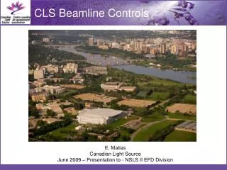
CLS Beamline Controls. E. Matias Canadian Light Source June 2009 – Presentation to - NSLS II EFD Division. The CLS Current System – EPICS Beamline Controls Next Step – EPICS & ScienceStudio. Where is Saskatoon?. 100. KSRS (124m). ANKA. SPEAR3 (240m). TLS-I. CLS (171m). PLS. MAX-II.

E N D
CLS Beamline Controls E. Matias Canadian Light Source June 2009 – Presentation to - NSLS II EFD Division
The CLS • Current System – EPICS Beamline Controls • Next Step – EPICS & ScienceStudio
100 KSRS (124m) ANKA SPEAR3 (240m) TLS-I CLS (171m) PLS MAX-II TLS-II 10 LSB Super-SOR BOOMERANG APS Emittance(nm·rad) ESRF ELETTRA BESSY-II Spring-8 SLS(240m) ALS ESRF SOLEIL(2006,354m) ELETTRA APS Spring-8 DIAMOND(2007,562m) NSLS-II 1 0 1 2 3 4 5 6 7 8 9 Energy(GeV) What are the CLS Objectives? • 170.88 m circumference • 2.9 GeV DBA lattice with 12-fold period • Nominal Tune: • x = 10.22 • y = 3.26 • Eloss per turn: > 0.876 MeV • Bend magnet radiation: • c = 1.6 Å • Ec = 7.6 keV • x = 18.1 nm•rad • Damping times: • x = 2.4 ms, y = 3.8 ms, E = 2.7 ms • ~10 mm bunch length
Phase 1 (operation): Total of 7 scientific and 2 diagnostics beamlines. Phase 2 (commissioning): Total of 7 additional beamlines and building expansion for medical imaging. Phase 3 (pre-design): Total of 7 additional beamlines and building expansion.
The CLS • Current System – EPICS Beamline Controls • Next Step – EPICS & ScienceStudio
EPICS Channel Access Protocol CA CA Detectors Cameras etc. IOC Operator Workstation User Applications CA Touch Panels Modbus TCP/IP CA IOC Telemecanique Momentum PLC CA State Machine Engine CA GPIB IOC CA IOC CA RS-232 VME CA IOC Single Board Computer
Beamline Controls Interfaces • EPICS Tools • Configuration Tool • User GUI & ROOT
Beamline Visualization - Raster scan with fluorescence spectroscopy of a pine needle contaminated with arsenic. The technique allows multiple elements to be detected simultaneously at each point of the raster. These images show distributions of arsenic, iron, and manganese, respectively, near the tip. The highest intensity displays in red, lowest in blue. - Custom on-line plotting application scripted in CERN Root, with data stream from the CLS data acquisition application. (G. Wright, R. Igarashi, K. Chang-Yong, N. Chen) As Map Fe Map
Traditional Beamline Visualization Cross section views of the beam spot intensity distribution for varying degrees of monochromator detuning (50-80%). (Only one image shown). (G. Wright, R. Igarashi, K. Chang-Yong, N. Chen)
Matlab • Sometimes used for prototyping (taking into account single threaded limitations)
Higher Level Tools Full Support: • EDM • CLS Scanning Tool • Qt (C/C++) • Root • Matlab • Java • synapps Partial Support: • Spec • Labview • Python • Tcl/Tk • Python • MEDM • synapps
The CLS • Current System – EPICS Beamline Controls • Next Step – EPICS & ScienceStudio
Scientific American May 2008 Science 2.0 – The Risk and Reward of Web-Based Research --------------------------------- “Our real mission isn’t to publish journals but to facilitate scientific communication” Timo Hannay – Head of Web Publishing at Nature Publishing Group
What Is the Web 2.0? • In plain English …. • Automating tedious tasks using web technology • Tools to help people and software collaborate
Team: People and Orgs Remote Control User Services System Deployment Integration System Requirements Testing Data Analysis/Grid Computing User Office Software Scientific Workflow Engines System Architecture
Team: People and Orgs Jinhui Qin Nathaniel Sherry (student) Mike Bauer Stewart McIntyre Marina Suominen Fuller Dionisio Medrano Dylan Maxwell Dong Liu Elder Matias Daron Chabot (now NSLS) Yuhong Yan Zahid Anwar (student) Chris Armstrong John Haley
Requirements • New User Office Functionality • Proposal submission • Peer review • User Feedback Tracking • Experiment Management • User Training/ Safety Testing • Remote Beamline Access • Integration with grid data-storage • Grid computing
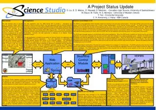
Web Application Beamline Control Module VESPERS HTTP JMS CA SAN DB System Architecture • VESPERS Beamline • EPICS control system • Beamline Control Module (BCM) • Web Application • Database • File Storage • Web Interface
Web Application Beamline Control Module VESPERS HTTP JMS CA SAN DB VESPERS Beamline • VESPERS — Very Sensitive Elemental and Structural Probe Employing Radiation from a Synchrotron • A bending magnet beamline on sector 6 at the Canadian Light Source synchrotron in Saskatoon, Saskatchewan. • A hard x-ray microprobe with an energy range of 6 to 30keV. • Techniques: X-Ray Fluorescence (XRF) & X-Ray Diffraction (XRD)
Web Application Beamline Control Module VESPERS HTTP JMS CA SAN DB EPICS Low-level Control System • EPICS — Experimental Physics and Industrial Control System • The standard control system at the CLS. • EPICS consists of a network of Input-Output Controls (IOCs) which are connected to directly to devices. • An IOC provides many Process Variables (PVs) which relate to either an input or output from a device and have a unique name. • Channel Access (CA) is used to read or write to any PV without knowing which IOC provides the PV. • More than 50,000 PVs in the CLS control system.
Web Application Beamline Control Module VESPERS HTTP JMS CA SAN DB Beamline Control Module (BCM) • The BCM provides a high-level interface to the low-level control system (EPICS). • Logical and physical separation of business logic and control logic. • Virtual device abstraction that provides independence from low-level control system. • Virtual devices can be logically organized into a device hierarchy. • Basic devices can be combined to build more functional devices. • Communication with external applications using two message queues (ActiveMQ).
Web Application Beamline Control Module VESPERS HTTP JMS CA SAN DB Web Application • A J2EE Servlet application that provides a web-based interface Science Studio. • Tools: Spring (MVC), iBATIS (ORM), JSecurity (Apache Ki), Apache Tomcat • Divided into two parts: the Core application and the VESPERS beamline application. • Core application is responsible for providing access to the business objects. • VESPERS application is responsible for remote control of the VESPERS beamline.
Web Application Beamline Control Module VESPERS HTTP JMS CA SAN DB Database • Metadata associated with the operation of a remote controlled beamline and the organization of experimental data collected on that beamline. • A project is the top level organizational unit and is associated with a project team. • A session defines a period of time allocated to a project team to conduct experiments. • An experiment relates a sample and the technique being applied to that sample. • A scan records the location of the acquired experimental data.
Web Application Beamline Control Module VESPERS HTTP JMS CA SAN DB Experimental Data Storage • Experimental data is stored at the CLS. • Common directory structure shared with other beamlines. • A large data storage facility is now operational at the University of Saskatchewan as part of WestGrid.
Web Application Beamline Control Module VESPERS HTTP JMS CA SAN DB VESPERS Web Interface • Rich web interface to Science Studio and the VESPERS beamline. • Designed to be used over commodity broadband internet. • Developed for the Firefox web browser without any additional plugins or extensions. • Known to work with other browsers, but requires the Canvas HTML tag. • AJAX is used for the VESPERS interface to provide device values in pseudo real time. • ExtJS, a JavaScript framework, provides many advanced GUI elements.
S: Kα Cr: Kα & Cr: Kβ Fe: Kα & Fe: Kβ Ni: Kα & Ni: Kβ X-Ray Fluorescence (XRF): Reveals Elemental Composition Characteristic Element Lines Selected and Mapped Over a 2D Scan Area 2D Maps Generated for Selected Elemental Lines
Peak Search X-Ray Diffraction (XRD): Reveals Structural Information Peak Fitting and Indexing of Image Set to Create a Grain Orientation Map Indexing Process Grain Orientations New C Programme – Matched Peak New C Programme – Expected Peak Old IDL Programme – Matched Peak Old IDL Programme – Matched Peak The XRD Indexing programme examines the locations of peaks in an image in order to determine the kind of lattice structure the samples constituent atoms are arranged in. Shown here are the results of an older indexing programme written in IDL, and the new indexing programme, written in C. The new indexing programme is proving to be more versatile, and more reliable than the old programme, often indexing sets of data that the old programme failed with.
User Office Workflow Example Prototype Implementation 1. CLS issues a call for proposals and gives deadline2. Beamline users submit proposals3. User Office administrator ends registration or extends deadline4. User Office administrator assigns proposals to user office reviewers5. Reviewers look at proposals and rank them6. User Office looks at ranking and chooses the proposals to accept7. Accepted proposals contact persons are notified8. Beamline User completes training (web service)9. After training is completed (simulated by a delay) the CLS is notified
The End Thank you.