Logical Database Design and the Relational Model (part 2)
550 likes | 1.07k Vues
Logical Database Design and the Relational Model (part 2). CS263 Lecture 6 . Step 5: map unary relationships. Unary relationships are relationships between the instances of a single entity type They are also called recursive relationships

Logical Database Design and the Relational Model (part 2)
E N D
Presentation Transcript
Logical Database Design and the Relational Model (part 2) CS263 Lecture 6
Step 5: map unary relationships • Unary relationships are relationships between the instances of a single entity type • They are also called recursive relationships • The approach to mapping is different for the two types one-to-many and many-to-many
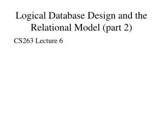
Unary one-to-many (1:N) relationships • A foreign key attribute is added within the same relation that references the primary key values (this foreign key must have the same domain as the primary key) • A recursive foreign key is a foreign key in a relation that references the the primary key values of that same relation • The following Fig. shows a unary one-to-many relationship ‘Manages’ that associates each employee with another employee who is their manager. Each employee has exactly one manager, and a given employee may manage zero to many employees
Unary one-to-many (1:N) relationships • The recursive foreign key in the relation is named Manager_ID • This attribute has the same domain as the primary key Employee_ID • Each row of this relation stores the following: • Employee_ID, Birthdate and Manager_ID. Notice that as it is a foreign key, Manager_ID references Employee_ID
Mapping a unary 1:N relationship (a) EMPLOYEE entity with Manages relationship (b) EMPLOYEE relation with recursive foreign key
Unary many-to-many (M:N) relationships • Here two relations are created, one to represent the entity type in the relationship and another representing the M:N relationship itself • The primary key of the associative relation consists of two attributes, both taking their values from the primary key of the other relation • Any non-key attribute of the relationship is included in the associative relation • The following Fig. illustrates this
Unary many-to-many (M:N) relationships • Here a bill-of-materials relationship among items that are assembled from other items or components is shown. • The relationship ‘Contains’ is M:N since a given item can contain numerous component items, and conversely an item can be used as a component in numerous other items
Unary many-to-many (M:N) relationships • The ITEM relation is mapped directly from the same identity type • COMPONENT is an associative relation whose primary key consists of two attributes that are arbitrarily named Item_No and Component_No • The attribute ‘Quantity’ is a nonkey attribute of this relation that for a given item records the quantity of a particular component used in the item • Notice that both Item_No and Component_No reference the primary key (Item_No) of the ITEM relation
Mapping a unary M:N relationship (a) Bill-of-materials relationships (M:N) (b) ITEM and COMPONENT relations
Unary many-to-many (M:N) relationships • We can easily query the above relation to determine the components of a given item • The following SQL query will list the immediate components (and their quantity) for an item number 100: SELECT Component_No, Quantity FROM COMPONENT WHERE Item_No = 100
Step 6: map ternary (and n-ary) relationships • It is best to convert a ternary relationship to an associative entity in order to represent participation constraints more accurately. Firstly, we create a new associative relation. The default primary key of this relation consists of the three primary key attributes for the participating entities (sometimes additional attributes are required to form a unique primary key) • These attributes then act in the role of foreign keys that reference the individual primary keys of the participating entity types . Any attributes of the associative entity type become attributes of the new relation
map ternary (and n-ary) relationships • The following Fig. Represents a PATIENT receiving a TREATMENT from a PHYSICIAN • The associative entity type PATIENT_Treatment has the attributes Date, Time and Results and values of these are recorded for each instance of patient treatment • The primary key attributes Patient_ID, Physician_ID and Treatment_Code become foreign keys in PATIENT_TREATMENT – these are components of its primary key but do not uniquely identify a given treatment, since a patient may receive the same treatment from the same physician on more than one occasion
map ternary (and n-ary) relationships • Does including the attribute ‘Date’ as part of the primary key (along with the other 3 attributes) result in a primary key? • This would be so if a patient only receives one treatment from a given physician on a given date • If this is not the case, we include Time as part of the primary key, which now consists of five attributes: Patient_ID, Physician_ID, Treatment_Code, Date and Time
Mapping a ternary relationship Ternary relationship with associative entity
Mapping the ternary relationship Remember that the primary key MUST be unique
Step 7: Map supertype/subtype relationships • Strategies to represent these in the relational model: • 1: Create a separate relation for each supertype and for each of its subtypes • 2: Assign to the relation created for the supertype the attributes that are common to all members of the supertype, including the primary key • 3: Assign to the relation for each subtype the primary key of the supertype, and only those attributes that are unique to that subtype • 4: Assign one (or more) attributes of the supertype to function as the subtype discriminator
Map supertype/subtype • The following 2 Figs. Show the supertype EMPLOYEE with subtypes HOURLY_EMPLOYEE, SALARIED_EMPLOYEE and CONSULTANT. The primary key of employee is Employee_Number and the attribute Employee_Type is the subtype discriminator • There is one relation for the supertype EMPLOYEE and one for each of the three subtypes, with the primary key for each of the four relations being Employee_Number. • A prefix is used to distinguish each of the primary keys, e.g. S_Employee_Number is the primary key the relation SALARIED_EMPLOYEE
Figure 5-21: Mapping Supertype/subtype relationships to relations
Map supertype/subtype • Each of these attributes is a foreign key that references the supertype primary key, as indicated by the arrows in the diagram. Each subtype relation contains only those attributes peculiar to the subtype • For each subtype a relation can be produced that contains all of the attributes (both specific and inherited). Supposing we want to display a table containing all the attributes of SALARIED_EMPLOYEE: SELECT * FROM EMPLOYEE, SALARIED EMPLOYEE WHERE Employee_Number = S_Employee_Number;
Introduction to normalisation • Normalisation = a formal process for deciding which attributes should be grouped together in a relation • It is the primary tool to validate and improve a logical design so that it satisfies certain constraints that avoid unnecessary duplication of data • Normalisation is the process of decomposing relations with anomalies to produce smaller, well-structured relations
Steps in normalisation • A normal form is a state of a relation that results from applying simple rules regarding functional dependencies (relationships between attributes) to that relation • First normal form: Any multivalued attributes (repeating groups) have been removed, so there is a single value (possibly null) at the intersection of each row and column of the table • Second normal form: Any partial functional dependencies have been removed • Third normal form: Any transitive dependencies have been removed
Steps in normalisation • Boyce/Codd normal form: Any remaining anomalies that result from functional dependencies have been removed • Fourth normal form: Any multivalued dependencies have been removed • Fifth normal form: Any remaining anomalies have been removed • Usually only bother with First to third • Following Fig shows process:
Functional dependencies and keys • Functional dependency = a constraint between two attributes or two sets of attributes • For a relation R, attribute B is functionally dependent on attribute A if for every valid instance of A, that value of A uniquely defines the value of B • If B is functionally dependent on A we write A B • The attribute on the left-hand side of the arrow is called a determinant
Functional dependencies and keys • An attribute may be functionally dependent on two or more attributes • e.g., the relation EMP_COURSE (Emp_ID, Course_Title, Date_Completed) can have its functional dependencies described as: • Emp_ID, Course_Title Date_Completed • i.e., the date a course is completed is completely determined by the identity of the employee and the title of the course
Functional dependencies and keys • Other examples: • VIN Make, Model, Colour, i.e. the make, model and colour of a vehicle are functionally dependent on the vehicle identification number • ISBN Title, First_Author_Name, i.e. the title of a book and the name of the first author are functionally dependent on the book’s ISBN
Candidate keys • Candidate key = an attribute or combination of attributes that uniquely identifies a row in a relation. Must satisfy the following properties: • Unique identification – for every row the value of the key must uniquely identify that row. This property implies that each nonkey attribute is functionally dependent on that key. • Nonredundancy – no attribute in the key can be deleted without destroying the property of unique identification
Candidate keys • Considering the previously-discussed EMPLOYEE1 (Emp_ID, Name, Dept_Name, Salary) relation, Emp_ID is the only determinant in this relation, and all the attributes are functionally dependent on it • Therefore Emp-ID is a candidate key, and since there are no other candidate keys it is also the primary key • For the relation EMPLOYEE2 (Following Figs.) note that Emp_ID does not uniquely identify a row in the relation • There are two functional dependencies in this relation: • Emp_ID Name, Dept_Name, Salary • Emp_ID, Course_Title Date_Completed
The EMPLOYEE2 relation Question – Is this a relation? Answer – Yes: unique rows and no multivalued attributes Question – What’s the primary key? Answer – Composite: Emp_ID, Course_Title
Candidate keys • The functional dependencies indicate that the combination of Emp_ID and Course_Title is the only candidate (composite) key (and therefore the primary key) for EMPLOYEE2, as neither uniquely identifies a row in this relation • We represent the functional dependencies in this relationship in the following Fig. (note here that Date_Completed is the only attribute that is functionally dependent on the full primary key consisting of the attributes Emp_ID and Course_Title)
Relationship between determinants and candidate keys • A candidate key is always a determinant, whilst a determinant may or may not be a candidate key • A candidate key is a determinant that uniquely identifies the remaining (nonkey) attributes in a relation • A determinant may be a candidate key, part of a composite candidate key or a nonkey attribute
First normal form (1NF) • First normal form = contains no multivalued attributes • Usually, when you map ER diagrams into relations, you remove multivalued attributes from entity types on the ER diagram, so there should not be any multivalued attributes remaining • However, many old legacy systems supported multivalued attributes, so we must understand how to get rid of them
Second normal form (2NF) • 2NF = already in 1NF and every nonkey attribute is fully functionally dependent on the primary key – thus no nonkey attribute is functionally dependent on part (but not all) of the primary key. If in 1NF will be in 2NF if any one of the following conditions applies:
2NF • The primary key consists of only one attribute(such as Emp_ID in EMPLOYEE1) • No nonkey attributes exist in the relation (thus all of the attributes in the relation are components of the primary key) • Every nonkey attribute is functionally dependent on the full set of primary key attributes
2NF • EMPLOYEE2 is an example of a relation that is not in 2NF • The primary key for this relation is the composite key Emp_ID and Course_Title. • Therefore the nonkey attributes Name, Dept_Name and Salary are functionally dependent on part of the primary key (Emp_ID) but not on Course_Title (see Fig.)
EmpID CourseTitle Name DeptName Salary DateCompleted EmpID, CourseTitle DateCompleted EmpID Name, DeptName, Salary Functional Dependencies in EMPLOYEE2 Dependency on entire primary key Dependency on only part of the key Therefore, NOT in 2nd Normal Form!!
Well-Structured Relations • A relation that contains minimal data redundancy and allows users to insert, delete, and update rows without causing data inconsistencies • Goal is to avoid anomalies • Insertion Anomaly – adding new rows forces user to create duplicate data • Deletion Anomaly – deleting rows may cause a loss of data that would be needed for other future rows • Modification Anomaly – changing data in a row forces changes to other rows because of duplication General rule of thumb: a table should not pertain to more than one entity type
2NF • Partial functional dependency = a functional dependency in which one or more nonkey attributes (such as Name) are functionally dependent on part (but not all) of the primary key • In EMPLOYEE2 this creates redundancy in that relation, which results in anomalies when that table is updated (as noticed previously: Insertion, Deletion and Modification anomalies)
Converting to 2NF • To do this we decompose the relation into new relations that satisfy one (or more) of the conditions described above. EMPLOYEE2 is decomposed into the following 2 relations: • 1: EMPLOYEE1 (Emp_ID, Name, Dept_Name, Salary). This satisfies the first condition above and is in 2NF • 2: EMP_COURSE (Emp_ID, Course_Title, Date_Completed) This satisfies the third property above and is also in 2NF
EmpID Name DeptName Salary EmpID CourseTitle DateCompleted Converting to 2NF Decomposed into two separate relations Both are full functional dependencies
Third normal form (3NF) • 3NF = already in 2NF and no transitive dependencies exist • Transitive dependency = a functional dependency between two (or more) nonkey attributes. • E,g. SALES(Cust_ID, Name, Salesperson, Region) – Cust_ID the primary key so that all the remaining attributes are functionally dependent on this • However there is a transitive dependency, as Region is dependent on Salesperson and Salesperson is dependent on Cust_ID • As a result there would be update anomalies for this
Relation with transitive dependency SALES relation with simple data
BUT CustID Salesperson Region Transitive dependency (not 3rd NF) Relation with transitive dependency CustID Name CustID Salesperson CustID Region All this is OK (2nd NF)
Anomalies • Insertion anomaly because a new salesperson assigned to the ‘North Region’ cannot be entered until a customer has been assigned, because a value for Cust_ID must be provided to insert a row in the table • Deletion anomaly because if customer 6837 is deleted from the table, we lose the information that salesperson Hernandez is assigned to the ‘East Region’ • Modification anomaly because if salesperson Smith is reassigned to the ‘East Region’, several rows must be changed to reflect that fact
Removing transitive dependencies • This can be done by decomposing SALES into two relations (see Following Figs.) • Salesperson, which is the determinant in the transitive dependency in SALES, becomes the primary key in SPERSON • Salesperson becomes a foreign key in SALES1 • Also uses less storage space because the dependent data (such as Region) do not have to repeat for each customer
Removing a transitive dependency (a) Decomposing the SALES relation
Relations in 3NF Salesperson Region CustID Name CustID Salesperson Now, there are no transitive dependencies… Both relations are in 3rd NF
Transitive dependencies • May also occur between sets of attributes in a relation • The relation SHIPMENT(Snum, Origin, Destination, Distance) could have a transitive dependency if the Distance attribute is functionally dependent on the pair of nonkey attributes Origin and Destination • We can remove the transitive dependencies by decomposing into 2 relations: • SHIPTO(Snum, Origin, Destination) • DISTANCES(Origin, Destination, Distance)
Other Normal Forms • Relations in 3NF are sufficient for most practical database applications, however 3NF does not guarantee that all anomalies have been removed • Boyce-Codd NF - All determinants are candidate keys…there is no determinant that is not a unique identifier • 4NF - No multivalued dependencies • 5NF - very rare • Domain-key NF - The “ultimate” NF…perfect elimination of all possible anomalies – practical utility quite limited