Display Technologies
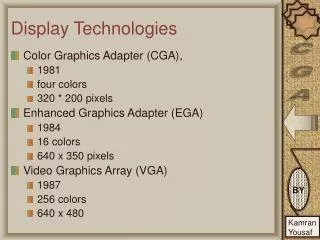
Display Technologies. Color Graphics Adapter (CGA), 1981 four colors 320 * 200 pixels Enhanced Graphics Adapter (EGA) 1984 16 colors 640 x 350 pixels Video Graphics Array (VGA) 1987 256 colors 640 x 480. New Technology. Extended Graphics Array (XGA) 1990

Display Technologies
E N D
Presentation Transcript
Display Technologies • Color Graphics Adapter (CGA), • 1981 • four colors • 320 * 200 pixels • Enhanced Graphics Adapter (EGA) • 1984 • 16 colors • 640 x 350 pixels • Video Graphics Array (VGA) • 1987 • 256 colors • 640 x 480
New Technology • Extended Graphics Array (XGA) • 1990 • 65536 / true color (16.8 million colors) • 800x600 • Ultra Extended Graphics Array (UXGA) • Mid 90’s • 16.8 million colors • 1600x1200 pixels • Digital data • digital-to-analog converter (DAC) • VGA cable.
Monitors DVI • Digital Video Interface (DVI) • VGA technology digital-to-analog • Degradation occurs. • DVI keeps data in digital form. • Eliminating signal loss. • Fine Piucture
Terminology • Dot Pitch • Distance between centers of two pixels • Resolution • No of pixels contained in a square inch • Multiple of X-axis, Y-axis and color depth • Refresh Rate • Time to draw a frame • Time to complete a pass
Color Depth • Bit-Depth - Number of Colors • 1 - 2 (monochrome) • 2 - 4(CGA) • 4 - 16(EGA) • 8 - 256(VGA) • 16 - 65,536(High Color, XGA) • 24 -16,777,216(True Color, SVGA) • 32 -16,777,216(True Color + Alpha Channel)
LCD Method • Liquid crystal molecules • Electric charge • Untwist ->No light pass • Twisted ->Light • Darker • Electrode
LCD - TFT • Active-matrix LCDs • Thin film transistors (TFT) • Switching transistors and capacitors. • Arranged in a matrix on a glass substrate. • Row is switched on • Charge is sent down the correct column • Capacitor at the designated pixel receives a charge. • Capacitor holds the charge until the next refresh • Untwist
Laser Printer • Static electricity • "temporary glue." • Photoreceptor drum • photoconductive material • total positive charge • Printer shines a tiny laser beam across the surface to discharge certain points. • laser "draws" the letters and images to be printed • Electrostatic image.
Ink Jet Printer • Small droplets of ink • Eextremely small (50 ~ 60 microns in diameter) • Resolutions up to 1440x720 dots per inch (dpi). • The dots can have different colors combined together to create photo-quality images.
Touch Screens • Input • Multiple types • Resistive • Capacitive • Surface acoustic wave • Output • Same as Monitor/LCD
Touch Screen - Resistive system • Glass Layer • Conductive and a resistive metallic layer. • Scratch-resistant layer • Electrical current • Two layers make contact in exact spot • Change in Electrical field • Change in the electrical field • Coordinates of the point of contact are calculated • Driver translates the touch • Transmits 75% of light
Touch Screens – Capacitive system • Electricaly charged layer • Glass panel of the monitor. • Touch -> Charge transferred. • Charge on the capacitive layer decreases. • Decrease is measured in circuits located at each corner of the monitor. • Driver Translates it. • Transmits almost 90% of the light. • Clear picture.
Touch Screens - Surface acoustic • Surface acoustic wave system • Transducers (one receiving and one sending) • Receiving transducer tell if the wave has been disturbed • Also locate it • No metallic layers on the screen • Transmits 100% light throughput • Perfect image clarity.
Scanners • Flatbed scanners • desktop scanners • commonly used. • Sheet-fed scanners • document moves • scan head immobile • looks like a printer. • Handheld scanners • user moves the scanner • Drum scanners • publishing industry • detailed images.
Parts of Scanner • Charge-coupled device (CCD) array • Mirrors • Scan head • Glass plate • Lamp • Lens • Cover • Filters • Stepper motor • Stabilizer bar • Belt • Power supply • Interface port (s) • Control circuitry
Scanner- Core Components • CCD • Array • most common • collection of tiny light-sensitive diodes • convert photons (light) into electrons (electrical charge). • photosites. • brighter the light, greater the electrical charge • Photomultiplier tube (PMT). • mounted on a glass cylinder. • Sensor at the center of the cylinder • splits light into three beams. • light is changed into an electrical signal.
Scanner Method • A lamp(CCFL/ xenon) illuminates the document. • mirrors, lens, filter and CCD array makes scan head. • scan head is moved slowly • Belt • Stepper motor • Stabilizer bar • Most scanners 300x300 dpi • number of sensors in a single row (x-direction sampling rate) of the CCD • precision of the stepper motor (y-direction sampling rate).