Servos
Servos. The material presented is taken from a variety of sources including: http://www.seattlerobotics.org/guide/servos.html , http://www.baldor.com/pdf/manuals/1205-394.pdf , and Parallax educational materials. Overview.

Servos
E N D
Presentation Transcript
Servos The material presented is taken from a variety of sources including: http://www.seattlerobotics.org/guide/servos.html, http://www.baldor.com/pdf/manuals/1205-394.pdf, and Parallax educational materials
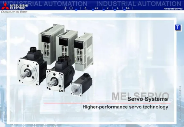
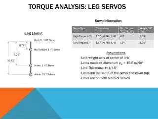
Overview • Servo motorsare used for angular positioning, such as in radio control airplanes. They typically have a movement range of 60 deg but can go up to 90 deg. • The output shaft of a servo does not rotate freely, but rather is made to seek a particular angular position under electronic control. • They are typically rated by torque and speed. A servo rated 40 ounce-in/.21 means that at 1 inch from the hub, the servo can exert 40 ounces of force and move 60 deg in 0.21 sec.
What makes a Servo • Servo motors and are constructed out of basic DC motors, by adding: • some gear reduction • a position sensor for the motor shaft • an electronic circuit that controls the motor's operation • The basic hobby servo has a 180:1 gear ratio. The motor is typically small. • Typically, a potentiometer (variable resistor) measures the position of the output shaft at all times so the controller can accurately place and maintain it’s setting.
Feed-back loop open-loop closed-loop
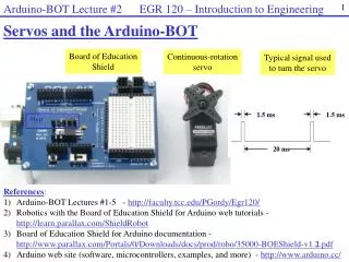
Control • An external controller (such as the Basic Stamp) tells the servo where to go with a signal know as pulse proportional modulation (PPM) or pulse code modulation (which isoften confused with pulse width modulation, PWM). • PPM uses 1 to 2ms out of a 20ms time period to encode its information.
PPM • A control wire communicates the desired angular movement. The angle is determined by the duration of the pulse applied to the control wire. • The servo expects to see a pulse every 20 milliseconds (.02 seconds). The length of the pulse will determine how far the motor turns. A 1.5 millisecond pulse will make the motor turn to the 90 degree position (often called the neutral position). • If the pulse is shorter than 1.5 ms, then the motor will turn the shaft to closer to 0 degrees. If the pulse is longer than 1.5ms, the shaft turns closer to 180 degrees.
PPM • The amount of power applied to the motor is proportional to the distance it needs to travel. So, if the shaft needs to turn a large distance, the motor will run at full speed. If it needs to turn only a small amount, the motor will run at a slower speed.
Modified Servos • Servo motors can also be retrofitted to provide continuous rotation: • Remove mechanical limit (revert back to DC motor shaft). • Remove pot position sensor (no need to tell position) and replace it with 2 equal-valued resistors with a combined resistance equivalent to that of the pot. This makes the servo “think” it is in the 90 deg position. Not always necessary
Modified Servos • The idea is to make the servo think that the output shaft is always at the 90 degree mark. • This is done by removing the feedback sensor, and replacing it with an equivalent circuit that creates the same readings as the sensor being at 90 degrees. • Then, giving it the signal for 0 degrees will cause the motor to turn on full speed in one direction. The signal for 180 degrees will cause the motor to go the other direction. • Since the feedback from the output shaft is disconnected, the servo will continue in the appropriate direction as long as the signal remains.
Parallax Servos • The parallax servos are modified servos with the potentiometer intact. • The potentiometer (a.k.a., pot) should be adjusted to make the servo think that it is at the 90 degree mark.
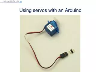
Parallax Servo Connections Servo Connector: Black – Vss Red – Vdd or Vin White – Signal
Servo on BOE Rev. C Adjust jumper to connect to Vin
Programming Servo Control The servos is controlled by bursts of signals spaced 20mS apart. A high signal can last between 1mS to 2mS. The PULSOUT instruction is used to send the signals:PULSOUT pin, durationpin: Defines which I/O pin to use.duration: defines how long the pulse should last, but it in NOT in mS.
PBASIC PULOUT command The PULSOUT duration is in 2 microsecond (uS) increments. 1 S = .000001 seconds.1 mS = 1000S For a command of: PULSOUT 14,750 This would be sending a pulse that lasts750 x 2 S = 1500 S or 1.5 mS on pin 14.