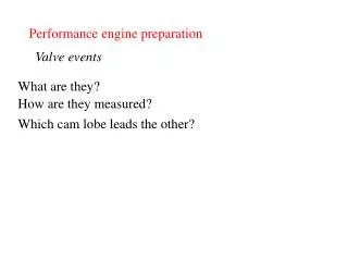
Performance Cylinder Head Preparation
Performance Cylinder Head Preparation. Power Production. Engine power is a result of the pressure developed by burning the fuel in the engine. There are generally four ways to increase engine power. Burn the fuel that is entering the engine more completely ( Burn (fuel) efficiency ).


Performance Cylinder Head Preparation
E N D
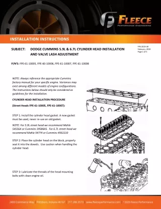
Presentation Transcript
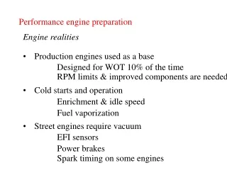
Power Production • Engine power is a result of the pressure developed by burning the fuel in the engine. • There are generally four ways to increase engine power. • Burn the fuel that is entering the engine more completely (Burn (fuel) efficiency). • Decrease the parasitic power losses within the engine. (mechanical efficiency) • Increase the thermal efficiency of the engine. • Increase the amount of fuel entering the engine (because the stoichiometric ratio for gasoline is 14.7:1 this means airflow must also be increased, or fuel efficiency will suffer). - volumetric efficiency
Air Density • Gasoline weighs approx 6 lbs/ gallon • Air weighs approx .0762525 lbs/ft3 • 6 lbs of fuel require 88.2 lbs of air to burn it at a 14.7:1 ratio • 88.2 lbs of air = 1156 ft3 of air • 1156 ft3 = 10.5 ft x 10.5 ft x 10.5 ft cube
Mechanical Efficiency • The mechanical efficiency of a typical engine is 90% 5% 7% 46% 42%
Power Production • Cylinder heads have a significant effect on three of the four methods for increasing engine power • Thermal efficiency • Burn (fuel) efficiency • Volumetric efficiency
Thermal Efficiency • Methods to improve thermal efficiency • Cast iron is less thermally conductive than aluminum • Thermally reflective coatings • Polishing the combustion chamber (reduces total surface area available for heat transfer) • Polish the piston top • Higher engine operating temperatures
Burn Efficiency • Factors affecting burn efficiency which the engine builder has little or no control over • Combustion chamber design • Overall port design • Factors which the engine builder has control over • Compression ratio • Intake port surface texture • Intake port design • Piston top design • Ignition timing • Camshaft timing
Compression Ratio • Ideally, the compression ratio should be as high as possible without encountering pre-ignition or detonation • Rule of thumb max compression with 92 octane fuel • 10:1 aluminum heads • 9.5:1 iron heads
Volumetric Efficiency • Volumetric efficiency is the ratio between the theoretical amount of airflow through the engine and the actual amount of airflow through the engine • Most stock engines are about 85% VE • The reduction in flow between actual and theoretical is due to flow obstructions and the limited time available for air to fill the cylinder
Volumetric Efficiency • Volumetric Efficiency (VE) = theoretical airflow ∻ actual airflow • Theoretical airflow = (RPM ∻ 2) x (displacement ∻ 1728) • Actual airflow must be measured with engine running on a dynamometer with a flow meter
Volumetric Efficiency • Estimated Actual Airflow • 1.67 x Horsepower = CFM (gasoline) • 1.47 x Horsepower = CFM (alcohol) • Volumetric Efficiency • (Gasoline) VE = (5600 x HP) (RPM x CID) • (Alcohol) VE = (4750 x HP) (RPM x CID)
Improving Volumetric Efficiency • The reduction in flow between actual and theoretical is due to flow obstructions and the limited time available for air to fill the cylinder • Flow obstructions may be removed by porting or altering the port/valve design (different cylinder heads) • The limited time issue is dealt with by using a longer duration, higher lift camshaft
Porting • Porting is a scientific trial and error method • Experience is the only way to become proficient • The area ½” below to ½” above the valve seat is the most critical for airflow • For street/strip use, ports should just be blended, the idea isn’t to remove a lot of material • 1 CFM gain will net approx. .43 HP gain
Porting Areas of Concern • A – Casting mark • B – Short side radius • C- Valve throat diameter • D – Valve guide • E – Sharp transition D C E
Porting • Steps • 1. Port match the intake • 2. Port match the exhaust • 3. Teardrop the valve guides • 4. Blend valve bowl/throat areas • 5. Polish the exhaust ports
Porting • Valve throat shout be approx. 85% valve diameter • Port cross section should be: • 85% valve area (street) • 90 % valve area (race) • Optimum port size should allow mixture to reach speed of 700 feet per second (477 mph)
Pressure Wave Tuning • The flow of air through the engine is not steady. • At 4000 RPM airflow past the valve starts and stops 33 times per second. • Peak port airspeeds can reach 700 feet per second. • The flow of air through the ports is influenced by pressure waves created by the opening and closing of valves.
Pressure Wave Tuning • As the valve closes, the fast moving air in the port slams into the back of the valve creating a high pressure are just behind the valve • This high pressure area rushes back towards the intake plenum leaving a low pressure area behind it • As the initial high pressure pulse escapes the intake runner into the plenum, a new high pressure area develops in the runner and travels back towards the valve.
Pressure Wave Tuning • These pressure pulses continue to “bounce” back and forth in the intake runner until the valve opens • If the intake system and camshaft are designed correctly, a positive pressure pulse will arrive at the back of the valve when the piston is approximately 70 degrees ATDC (peak piston speed) • This high pressure pulse aids in cylinder filling and in a properly designed race engine can cause the VE to exceed 100% • The time it takes these pressure pulses to travel the length of the intake runner is known and can be used to calculate the optimum intake runner length
Pressure Wave Tuning The formula for optimum intake runner length (L) is: L = ((ECD × 0.25 × V × 2) ÷ (rpm × RV)) - ½D Where: ECD = Effective Cam Duration (720 - Duration @ .050”) RV = Reflective Value (# of pressure wave) D = Runner Diameter V= Pressure wave speed (1250 fps – 1300 fps)
Intake Runner Cross-section Area • The intake runner cross-section area should be approx. 80% the area of the valve • Cross-section area = (valve diameter)2 x .6126
Exhaust Pipe Tuning • The same pressure wave tuning that was done in the intake can also be done on the exhaust, but instead of a positive pressure pulse we want a negative pressure pulse to arrive at the open valve • Pressure wave tuning assists in exhaust scavenging
Exhaust Pipe Tuning Optimum Header Pipe Length Calculation HPL = 850 x (360-EVO) RPM - 3
Header Pipe Diameter SCID x 13.38 HPD = (HPL + 3) x 25 HPD = Header pipe diameter SCID = Single cylinder displacement HPL = Header pipe length
Exhaust Pipe Tuning Optimum Header Collector Diameter HCD = 1.9 x HPD HCD = Header Collector Diameter HPD = Header Pipe Diameter
Exhaust Pipe Tuning Optimum Header Collector Length HPL x .5 = HCL Header Pipe Length = HPL Header Collector Length = HCL