Download
1 / 67
810 likes | 3.44k Vues
CHAPTER 26 CYLINDER HEAD AND VALVEGUIDE SERVICE. OBJECTIVES. After studying Chapter 26, the reader should be able to: Prepare for ASE Engine Repair (A1) certification test content area “B” (Cylinder Head and Valve Train Diagnosis and Repair). Identify combustion chamber types.

E N D
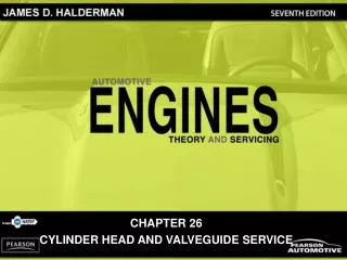
CHAPTER 26 CYLINDER HEAD AND VALVEGUIDE SERVICE
OBJECTIVES After studying Chapter 26, the reader should be able to: • Prepare for ASE Engine Repair (A1) certification test content area “B” (Cylinder Head and Valve Train Diagnosis and Repair). • Identify combustion chamber types. • List the steps necessary to recondition a cylinder head. • Describe how to inspect and measure valve guides. • Discuss valve guide repair options.
Arithmetic average roughness height (RA) Bend Bronze guide liners Bronze guides Cam tunnel Cast-iron guides Concentric Crossflow head Distortion Fire deck Milling Oversize (OS) stems Port Porting (relieving) Quench area Root-mean-square (RMS) Siamese port Spiral bronze alloy bushing Squish area Surface grinder Surface-to-volume ratio Thin-walled bronze alloy sleeve bushing Twist Unshrouding Valve duration Valve guide knurling Valve guides Valve seat inserts Valve shrouding Warpage KEY TERMS
INTRODUCTION • The repair and reconditioning of cylinder heads represents the most frequent engine repair operation of any engine component. • The highest temperatures and pressures in the entire engine are located in the combustion chamber of the cylinder head. • Its valves must open and close thousands of times when the engine is operated.
CYLINDER HEADS • CONSTRUCTION • DESIGN FEATURES • Squish area • Quench area • Spark plug placement • Surface-to-volume ratio • Valve shrouding • Crossflow valve placement • COMBUSTION CHAMBER DESIGNS • Wedge • Pentroof • Hemi • FOUR-VALVE CYLINDER HEADS
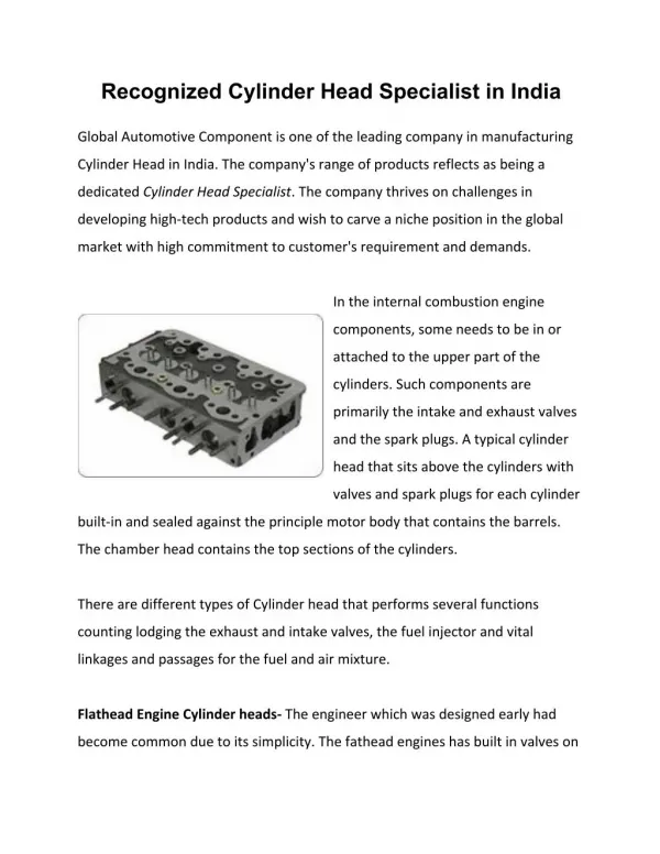
FIGURE 26–1 The seats and guides for the valves are in the cylinder head as well as the camshaft and the entire valve train if it is an overhead camshaft design. CYLINDER HEADS
FIGURE 26–2 A wedge-shaped combustion chamber showing the squish area where the air-fuel mixture is squeezed, causing turbulence that pushes the mixture toward the spark plug. CYLINDER HEADS
FIGURE 26–3 Locating the spark plug in the center of the combustion chamber reduces the distance the flame front must travel. CYLINDER HEADS
FIGURE 26–4 The combustion chamber of the 5.7 liter Chrysler Hemi cylinder head shows the two spark plugs used to ensure rapid burn for best power and economy with the lowest possible exhaust emissions. CYLINDER HEADS
What Is Carbon Knock? • Carbon knock was a common occurrence in older engines that were equipped with carburetors and high compression ratios. As carburetors aged, the mixture would tend to be richer than normal, due to a leaking needle and seat, as well as a fuel-saturated float. This richer mixture would often cause carbon deposits to form in the combustion chamber. During light load conditions when the spark advance was greatest, a spark knock would occur, caused by a higher compression ratio due to the carbon deposits. This knocking was often very loud, sounding like a rod bearing noise, because in some cases the carbon deposits actually caused physical contact between the piston and the carbon. Many engines were disassembled in the belief that the cause of the knocking sound was a bearing, only to discover that the bearings were okay.
What Is Carbon Knock? • Carbon knock can still occur in newer engines, especially if there is a fault in the fuel system that would allow a much richer-than-normal air-fuel mixture, causing excessive carbon deposits to form in the combustion chamber. Often a decarbonization using chemicals will correct the knocking.
FIGURE 26–5 The shrouded area around the intake valve causes the intake mixture to swirl as it enters the combustion chamber. CYLINDER HEADS
FIGURE 26–6 A typical cross flow cylinder head design, where the flow into and out of the combustion chamber is from opposite sides of the cylinder head. CYLINDER HEADS
FIGURE 26–7 Method for measuring the valve opening space. CYLINDER HEADS
FIGURE 26–8 Comparing the valve opening areas between a two- and three-valve combustion chamber when the valves are open. CYLINDER HEADS
FIGURE 26–9 Typical four-valve head. The total area of opening of two small intake valves and two smaller exhaust valves is greater than the area of a two-valve head using much larger valves. The smaller valves also permit the use of smaller intake runners for better low-speed engine response. CYLINDER HEADS
FIGURE 26–10 Four valves in a pentroof combustion chamber. CYLINDER HEADS
INTAKE AND EXHAUST PORTS • PURPOSE AND FUNCTION • INTAKE PORTS • EXHAUST PORTS
Horsepower Is Airflow • To get more power from an engine, more air needs to be drawn into the combustion chamber. One way to achieve more airflow is to increase the valve and port size of the cylinder heads along with a change in camshaft lift and duration to match the cylinder heads. One popular, but expensive, method is to replace the stock cylinder heads with high-performance cast-iron or aluminum cylinder heads. • Some vehicle manufacturers, such as Audi, go to great expense to design high-flow rate cylinder heads by installing five-valve cylinder heads on some of their high-performance engines.
FIGURE 26–11 An Audi five-valve cylinder head, which uses three intake valves and two exhaust valves. Horsepower Is Airflow
Unshroud the Intake Valve for More Power • If an engine is being rebuilt for high performance, most experts recommend that the shrouded section around the intake valve be removed, thereby increasing the airflow and, therefore, the power that the engine can achieve, especially at higher engine speeds. This process is often called unshrouding.
FIGURE 26–12 The intake manifold design and combustion chamber design both work together to cause the air-fuel mixture to swirl as it enters the combustion chamber. INTAKE AND EXHAUST PORTS
FIGURE 26–13 A port-injected engine showing the straight free-flowing intake and exhaust ports. INTAKE AND EXHAUST PORTS
FIGURE 26–14 A cutaway head showing the coolant passages in green. CYLINDER HEAD PASSAGES • COOLANT FLOW PASSAGES • HEAD GASKET HOLES • LUBRICATING OIL PASSAGES
FIGURE 26–15 Coolant flows through the cylinder head, and the passages are sealed by the head gasket. CYLINDER HEAD PASSAGES
CYLINDER HEAD SERVICING • CYLINDER HEAD SERVICING SEQUENCE • DISASSEMBLING OVERHEAD CAMSHAFT HEAD • VALVE TRAIN DISASSEMBLY • CYLINDER HEAD INSPECTION
FIGURE 26–16 Overhead camshafts may be (a) held in place with bearing caps, (b) supported by towers, or (c) fitted into bearing bores machined directly into the head. CYLINDER HEAD SERVICING
FIGURE 26–17 Always follow the specified loosening sequence to prevent valve spring tension from bending the camshaft. CYLINDER HEAD SERVICING
FIGURE 26–18 Pushrods can be kept labeled if stuck through a cardboard box. Individual parts become worn together. Using cardboard is a crude but effective material to keep all valve train parts together and labeled exactly as they came from the engine. CYLINDER HEAD SERVICING
FIGURE 26–19 Cylinder heads should be checked in five planes for warpage, distortion, bend, and twist. CYLINDER HEAD SERVICING
FIGURE 26–20 A precision ground straightedge and a feeler gauge are used to check the cylinder head for flatness. CYLINDER HEAD SERVICING
FIGURE 26–21 Warped overhead camshaft cylinder head. If the gasket surface is machined to be flat, the camshaft bearings will still not be in proper alignment. The solution is to straighten the cylinder head or to align bore the cam tunnel. ALUMINUM CYLINDER HEAD STRAIGHTENING • PURPOSE AND FUNCTION
FIGURE 26–22 A cast-iron cylinder head being resurfaced using a surface grinder. CYLINDER HEAD RESURFACING • REFINISHING METHODS • Two common resurfacing methods are: • Milling or broaching • Grinding • SURFACE FINISH
FIGURE 26–23 A graph showing a typical rough surface as would be viewed through a magnifying glass. RA is an abbreviation indicating the average height of all peaks and valleys. CYLINDER HEAD RESURFACING
The Potato Chip Problem • Most cylinder heads are warped or twisted in the shape of a typical potato chip (high at the ends and dipped in the center). After a cylinder head is ground, the surface should be perfectly flat. A common problem involves grinding the cylinder head in both directions while it is being held on the table that moves to the left and right. Most grinders are angled by about 4 degrees. The lower part of the stone should be the cutting edge. If grinding occurs along the angled part of the stone, then too much heat is generated. This heat warps the head (or block) upward in the middle. The stone then removes this material, and the end result is a slight (about 0.0015 in.) depression in the center of the finished surface. To help prevent this from happening, always feed the grinder in the forward direction only (especially during removal of the last 0.003 in. of material).
FIGURE 26–24 The material that must be removed for a good manifold fit. INTAKE MANIFOLD ALIGNMENT • PURPOSE • PROCEDURE
FIGURE 26–25 Using an intake manifold template to check for the proper angles after the cylinder heads have been machined. INTAKE MANIFOLD ALIGNMENT
VALVE GUIDES • TYPES • VALVE STEM-TO-GUIDE CLEARANCE • MEASURING VALVE GUIDES • OVERSIZE STEM VALVES
FIGURE 26–26 An integral valve guide is simply a guide that has been drilled into the cast-iron cylinder head. VALVE GUIDES
FIGURE 26–27 All aluminum cylinder heads use valve guide inserts. VALVE GUIDES
FIGURE 26–28 Valve guides often wear to a bell-mouth shape to both ends due to the forces exerted on the valve by the valve train components. VALVE GUIDES
FIGURE 26–29 A small-hole gauge and a micrometer are being used to measure the valve guide. The guide should be measured in three places: at the top, middle, and bottom. VALVE GUIDES
FIGURE 26–30 The diameter of the valve stem is being measured using a micrometer. The difference between the inside diameter of the valve guide and the diameter of the valve stem is the valve guide-to-stem clearance. VALVE GUIDES
FIGURE 26–31 Measuring valve guide-to-stem clearance with a dial indicator while rocking the stem in the direction of normal thrust. The reading on the dial indicator should be compared to specifications because it does not give the guide-to-stem clearance directly. The valve is usually held open to its maximum operating lift. VALVE GUIDES
Tight Is Not Always Right • Many engine manufacturers specify a valve stem-to-guide clearance of 0.001 to 0.003 in. (0.025 to 0.076 mm). However, some vehicles, especially those equipped with aluminum cylinder heads, may specify a much greater clearance. For example, many Chrysler 2.2 liter and 2.5 liter engines have a specified valve stem-to-guide clearance of 0.003 to 0.005 in. (0.076 to 0.127 mm). This amount of clearance feels loose to those technicians accustomed to normal valve stem clearance specifications. Although this large amount of clearance may seem excessive, remember that the valve stem increases in diameter as the engine warms up. Therefore, the operating clearance is smaller than the clearance measured at room temperature. Always double-check factory specifications before replacing a valve guide for excessive wear.
What Is Valve Guide Knurling? • In an old and now outdated process known as valve guide knurling, a tool is rotated as it is driven into the guide. The tool displaces the metal to reduce the hole diameter of the guide. Knurling is ideally suited to engines with integral valve guides (guides that are part of the cylinder head and are nonremovable). It is recommended that knurling not be used to correct wear exceeding 0.006 in. (0.15 mm). In the displacing process, the knurling tool pushes a small tapered wheel or dull threading tool into the wall of the guide hole. This makes a groove in the wall of the guide, similar to a threading operation without removing any metal.
What Is Valve Guide Knurling? • The metal piles up along the edge of the groove just as dirt would pile up along the edge of a tire track as the tire rolled through soft dirt. (The dirt would be displaced from under the wheel to form a small ridge alongside the tire track.)
What Is Valve Guide Knurling? • The knurling tool is driven by an electric drill and an attached speed reducer that slows the rotating speed of the knurling tool. The reamers that accompany the knurling set will ream just enough to provide the correct valve stem clearance for commercial reconditioning standards. The valve guides are honed to size in the precision shop when precise fits are desired. Clearances of knurled valve guides are usually one-half of the new valve guide clearances. Such small clearance can be used because knurling leaves so many small oil rings down the length of the guide for lubrication.
FIGURE 26–32 Sectional view of a knurled valve guide. What Is Valve Guide Knurling?
VALVE GUIDE REPLACEMENT • PURPOSE • VALVE GUIDE SIZES • VALVE GUIDE INSERTS • SPIRAL BRONZE INSERT BUSHINGS