Chapter 12 Local Area Networks
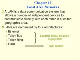
Chapter 12 Local Area Networks. A LAN is a data communication system that allows a number of independent devices to communicate directly with each other in a limited geographic area. LANs are dominated by four architectures: Ethernet Token Bus Token Ring FDDI. Standards of IEEE and part of

Chapter 12 Local Area Networks
E N D
Presentation Transcript
Chapter 12Local Area Networks • A LAN is a data communication system that allows a number of independent devices to communicate directly with each other in a limited geographic area. • LANs are dominated by four architectures: • Ethernet • Token Bus • Token Ring • FDDI Standards of IEEE and part of Its project 802 ANSI standard
Project 802 • It is a way of specifying functions of the physical layer, the data link layer, and the network layer to allow for • interconnectivity and compatibility of different LANs • Data to be exchanged across incompatible networks
Project 802 • It has subdivided the data link layer into 2 sub layers • Logical Link Control LLC • Medium Access ControlMAC • LLC is non-architecture-specific, that is, it is the same for all IEEE–defined LANs • The MAC sub layer, contains a number of distinct modules; each carries proprietary information specific to the LAN product being used
IEEE 802.2 LLC protocol It contains the end-user portions of the frame: Logical address Control information Data MAC It resolves the contention for the shared media. It contains the following specifications necessary to move information: Physical address Synchronization Flag Flow control Error control IEEE Project 802 modeltakes the structure of HDLC frame and divides into two sets of functions
Protocol Data Unit PDU • The data unit in the LLC level is called PDU. • It contains four fields familiar to HDLC • DSAP used to identify the protocol stacks on R/S stations • SSAP • Control field • Information field • The PDU has no flag fields, no CRC, and no station address, these fields are added in the MAC layer
Ethernet (IEEE 802.3) • It defines two categories • Baseband -Specifies a digital signal • Broadband - Specifies an analog signal
Access Method CSMA/CD • Whenever multiple users have unregulated access to a single line, there is a danger of signals overlapping and destroying each other. • Such overlaps, which turn the signals into unusable noise, are called collisions. • A LAN therefore needs a mechanism to minimize the number of collisions, and maximize the number of frames that are delivered successfully. • This mechanism is called carrier sense multiple access with collision detection (CSMA/CD).
Figure 12-13-continued 1BASE5
Figure 12-14 WCB/McGraw-Hill
Token Ring (802.5) • Token ring resolves the problem of multiple stations tries to capture the link at the same time. • Each station may transmit only during its turn and may send one frame per turn
Access Method • The mechanism that coordinates this turn is called Token Passing • Whenever the network is unoccupied, it circulates a 3-byte token. • This token is passed from NIC to NIC in sequence until it encounters a station with data to send. • The station waits for the token to enter its network board. • If the token is free, the station may then send a data frame. • It keeps the token and sets a bit inside its NIC as a reminder that it has done so, then it sends its one data frame. • The data frame proceeds around the ring, being regenerated by each station
Each intermediate station examines the destination address, finds that the frame is addressed to another station, and relays it to its neighbor. • The intended recipient recognizes its own address, copies the message, checks for errors, and changes 4 bits in the last byte of the frame to indicate address recognized and frame copied. • The full packet then continues around the ring until it returns to the station that sent it. • The sender receives the frame and recognizes itself in the source address field. It then examines the address-recognized bits. If they are set, it knows the frame was received. • The sender then discards the used data frame and releases the token back to the ring.
Token Passing Figure 12-15
Token Passing Figure 12-15-continued
Token Passing Figure 12-15-continued
Token Passing Figure 12-15-continued
Token Ring Frame Figure 12-16
Priority and Reservation • Once the token has been released, the next station on the ring with data to send has the right to take charge of the ring. • In IEEE 802.5 model, it is possible that a busy token can be reserved by a station waiting to transmit, regardless of the station location on the ring. • Each station has priority code. As a frame passed by a station waiting to transmit may reserve the next open token by entering its priority code in the Access control field (AC) of the token or the data frame • A station with a higher priority may remove a lower priority reservation and replace its own. • If station has equal priority, the process is 1st–come, 1st–serve
Monitor Stations • One station on the ring is designated as a monitor station. • The monitor sets a timer each time the token passes. • If the token does not appear in the allotted time, it is presumed to be lost and the monitor generates a new token and introduce it to the ring. • The monitor guards against recirculation data frames by setting a bit in AC field of each frame. • As a frame passes, the monitor checks the status field. • If the status bit is set, it knows that the packet has already been around the ring and should be discarded. • If the monitor fails, a second station, designated as back up, takes over
Token Frame Is a placeholder and reservation frame. • SD: indicates frame is coming • AC: indicates that frame is a Token and includes the priority & reservation fields. • ED: indicates the end of the frame
Abort Frame • Generated by the sender to stop its own transmission or by the monitor to purge an old transmission. • Token and Abort frames are both truncated data/command frames.
Token Ring Figure 12-18
Implementation of the Ring: • The ring in a Token ring consists of a series of shielded twisted-pair sections linking each station to its immediate neighbors. • Each station connects an output port on one section to an input port on the next, creating a ring with one direction traffic flow. • A frame is passed to each station in sequence, where it is examined, regenerated, and then sent on to the next station. Note • If a node is disabled, it could stop the flow of traffic around the entire network. • To solve the problem, each station is connected to an automatic switch. The switch can bypass an inactive station. • Individual automatic switches are combined into a hub called a (MAU) multi station access unit, which can support up to 8 stations.
Token Ring Switch Figure 12-19
MAU Figure 12-20
A token ring network consists of a logical ring implemented in a physical ring topology. • A token, which is a special frame, and data are transmitted in a point-to-point manner from one node (called a lobe) to the next. • The direction of circulation is fixed and either clockwise or counterclockwise (but not both). E.g, on a counterclockwise rotating ring, if lobe 3 has a “free” token & wants to send data to lobe 2, data frames must circulate the ring in the order 3-4-5-1-2. On a clockwise rotating ring, though, the transmission order is 3-2.
(a) A typical token ring network consists of lobes connected to a hub in a physical star configuration (b) Internally, lobes are actually interconnected via a logical ring
Example of a typical token ring network configuration. • Token ring hubs are called multistationaccess units (MAUs), and nodes are called lobes. • Physically, Nodes are connected to an MAU in a star configuration. Within an MAU, however, a logical ring topology exists. • Lobes are connected to the ring using an IBM Data Connector, which enables lobes to be removed without disrupting the ring. MAUs also can be interconnected using special “ring in/ring out” ports, which preserve the ring structure. Note the presence of relay switches within each hub. Relay switches (also called bypass switches) are used to maintain the integrity of the ring in the event of Node failure. E.g: if Node 12 stops working or if there is a break in the cable connecting Node 12 to the ring, the ring is broken. In such instances, the relay switch closes, thus preserving the ring.
Incorporated within the backbone, a token ring switch acts as a multiport source routing bridge and enables large networks to be partitioned into smaller segments.
Fiber Distributed Data Interface • FDDIIs a LAN protocol implemented by ANSI. • It supports data rates of 100 Mbps • When FDDI was designed, speeds of 100 Mbps required fiber-optic cable. • Today, however, this speed is available using copper cable. The copper cable of FDDI is known as CDDI.
FDDI Rings • Is implemented as a dual ring (primary & secondary) • secondary is provided in case the primary fails. • Whenever a problem occurs on the primary ring, the secondary can be activated to complete the data circuits and maintain service. • Nodes connect to both rings using (MIC) media Interface connector
FDDI’s counter-rotating ring architecture. • The primary ring is active in normal operation; the • secondary ring provides redundancy. • All devices on the ring are: • dual-attachment stations or dual-attachment hubs.
FDDI’s “self-healing” capability. In the event of a fiber cut or an inoperative node, a FDDI network automatically “heals” itself by wrapping the ring at the point of failure. This is done by interconnecting the primary and secondary rings into a single functional ring.
Access Method • Token passing, and is limited by time. • A station may send as many frames as it can within its allotted access period, given that real-time data sent first.
FDDI defines 3 time registers to control circulation of the token Values are set when the ring is initialized. • Synchronous Allocation (SA): This register indicates the length of time allowed each station for sending synchronous data (real-Time). Which is different for each station. 2. Target Token Rotation Time; (TTRT) Indicates the average time required for a token to circulate around the ring exactly once. • Absolute Maximum Time (AMT); This register holds a value = 2*TTRT. Token may not take longer than this time to make one rotation of the ring. If it does, the ring must be initialized.
FDDI defines 3 types of nodes • Dual attachment station (DAS) • has two MIC (media Interface connector) • requires NIC with 2 inputs & 2 out puts • Faults are bypassed by station’s making connection from the primary ring to secondary to switch signals from one input to another output
Single attachment station (SAS) • SAS has 1 MIC (media Interface connector) • can connect only one ring. • Robustness is achieved by connecting SAS to (DACs), rather than to the FDDI ring directly. • This configuration allows each workstation to operate through a NIC with only one input and one output. The connector (DAC) provides the connection to the dual ring.
Standards • Different architectures could restrict the growth of networking. • The Institute of Electrical and Electronic Engineers (IEEE) developed computer network architecture standards. • The IEEE efforts were called Project 802. • There are three dominant standards • Ethernet (802.3) • Token ring (802.5) • Wireless (802.11).