Engine Lower End and Lubrication System Theory
430 likes | 797 Vues
Engine Lower End and Lubrication System Theory. Chapter 19. Objectives. Describe the related theory of all of the parts that make up the lower end Tell how a cylinder block is made and understand the functions of its parts

Engine Lower End and Lubrication System Theory
E N D
Presentation Transcript
Objectives • Describe the related theory of all of the parts that make up the lower end • Tell how a cylinder block is made and understand the functions of its parts • Understand how pistons are constructed and the reasons behind their various designs
Objectives (cont'd.) • Discuss the various types of piston rings and be able to make the correct choice when selecting rings for a rebuilt engine • Understand the differences in the various types of engine bearings • Describe the parts of the crankshaft and their functions
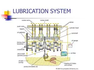
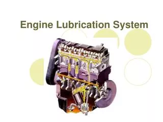
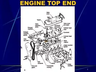
Introduction • Lower end consists of: • Crankshaft assembly • Piston • Rod • This chapter describes: • Lower end parts • Engine block • Lubrication system
Cylinder Block Construction • Cast using cast iron or aluminum • In a mold called a core • Core is supported around outside of core box • Leaves core holes in finished block • Molten iron poured into core box • Heat of casting process cooks the sand • Casting cools and sand breaks up • Casting is shaken out • Remaining sand washed way through core holes • Core holes closed off with core plugs
Core Plugs • Usually made of steel • Brass, rubber, stainless steel, or copper expandable are also used • Brass and stainless steel are superior in marine environment • Do not rust • Not used in new cars because of cost • Not needed because coolant prevents rust • Also known as expansion plugs, welsh plugs, freeze plugs, or soft plugs
Cylinder Bore • Cylinders are bored in the block • Engines today: little cylinder wall wear • Cylinder bore taper wear • Forms the ring ridge at the top of ring travel • Causes of cylinder bore taper wear • High pressure of piston rings against cylinder wall • Top of cylinder receives less lubrication • Out-of-round wear • Results when piston tilts from one side to the other
Cylinder Sleeves • Aluminum blocks • Usually have permanently installed iron cylinder sleeves • Sleeves • Replaceable cylinder bores • Damaged cylinders can be bored oversize • Accept a pressed-fit dry sleeve • Wet sleeves • Only contact block at upper and lower ends
Main Bearing Caps • Main bearing bores • Bored at the factory with bearing caps in place • Main caps are not interchangeable
Lifter Bores • Bored in the block on engines with camshafts in the block • Lifters spin in the lifter bores • Very little clearance to the lifters • Just enough to allow oil to leak below to lubricate camshaft lobes
Crankshaft Design • Journals: polished bearing surfaces • Main bearing journals: support crankshaft as it turns • Rod bearing journals: offset from main bearing journal centerline • Counterweight opposite each rod journal: balances offset rod journals and rod • Crankshafts are cast or forged • Forged cranks: stronger, but cost more • Cast crankshafts: larger counterweights
Crankshaft End Thrust • Crankshaft is pushed forward by pressure of end thrust • End thrust is exerted by: • Torque converter • Release spring pressure of clutch • Thrust surfaces • Precision bearing surface ground on sides of crankshaft main bearings • Flanged thrust bearing • Fits between crankshaft thrust surfaces
Direction of Crankshaft Rotation • Most automotive engine crankshafts rotate counterclockwise • Except Hondas and Hyundais • Transverse mounted engines follow this standard • Longitudinal mounted engine • Turns clockwise
Vibration Damper • During combustion: crankshaft twists and overcorrects in the other direction • Torsional vibration causes crankshaft to break • Timing chain and sprocket wear result • Most vibration occurs at front of the crankshaft • Vibration damper (i.e., harmonic balancer) • Dampens torsional vibration • Heavy outer inertia ring and inner hub separated by a synthetic rubber strip
Crankshaft Hardness • Some crankshafts are hardened • Mostly imports and heavy-duty manufacturers • Must be rehardened if reground • Crankshafts that have not been hardened will suffer misalignment if rehardened • Most crankshafts tend to work-harden with use • Used, polished crankshaft will have yellow tint
Bearings • Crankshaft bearings • Usually two-piece plain bearings with a specially designed surface • Bearing inserts • Made from many different materials • Bearing properties • Embeddability, conformability, and fatigue strength • Inserts are positioned in the bearing bore by a locating lug or dowel
Bearings (cont'd.) • Bearing spread • Measurement across parting face slightly larger than diameter of bearing bore • Bearing crush • Bearing extends above parting line of bearing bore half by about .0005”–.00015” • Bearings come in standard sizes and undersizes • Undersized: used when crankshaft reground • Cam bearings: often made from seamless steel tubing with lining bonded to the inside
Connecting Rods • Made from forged or cast steel formed in an I-beam shape • Forged rods: stronger • Rod caps are not interchangeable • Oil clearances of bearings vary greatly • Rod oil holes • Squirt oil on the cylinder wall • Nearly all engines are left-hand • When a left-hand engine has oil-spit holes they are to the right when the notches face forward
Pistons • Today’s pistons • Cast or forged aluminum • Undergo remarkable stresses
Piston Head and Ring Grooves • Piston head (crown) is round • Skirt is usually oval • Diameter of head • Smaller than diameter of skirt • Piston ring grooves • Top piston ring is positioned as high as possible on piston • Holes in the oil ring groove allow excess cylinder wall oil to return to the crankcase
Heat Transfer • Piston crown heat • Transferred through piston rings to water jackets • Some manufacturers use different piston head shapes to allow compression ratio variation • High compression pistons can only be installed in one direction in the cylinder
Cast and Forged Pistons • Cast aluminum pistons: most common • Forged pistons: available for heavy-duty or high-performance use • Dense grain structure • 70% stronger than cast pistons • Hypereutectic pistons: cannot withstand tensile loads • Better wear characteristics
Piston Skirt • Aluminum • Expands at twice the rate of cast-iron • To control expansion: • Taper the piston • Piston skirt is cam ground • Struts of spring-loaded steel cast into them • Trunk piston • Full-skirt piston used on longer stroke engine • Slipper-skirt • Designed to clear the crankshaft counterweights
Piston Pin Offset and Piston Pins • Piston pin offset and height • Different configurations • Piston pins • Attach piston to connecting rod • Piston pin types • Pressed-fit in rod • Full-floating
Piston Rings • Most engines use two compression rings and one oil ring • Top ring: exposed to flame of combustion during every power stroke • Piston rings: • Seal combustion pressures • Help cool piston • Control oil consumption
Compression Rings • Forced against cylinder wall by combustion pressure at top and back of ring • Top ring controls sealing of combustion • Second rings captures pressure that escapes • Cast in groups • Installed on a mandrel and machined out of round • Low-tension rings • Introduced to improve fuel economy
Compression Ring Materials and Coatings • Most rings: made of plain cast iron • Cast iron rings: used in re-ring jobs • Moly rings: have groove machined on their faces • Chrome rings: last the engine life with no wear • Premium ring combination: • Moly barrel-faced top ring • Reverse-torsion second ring • Three-piece chrome oil ring
Compression Ring Materials and Coatings (cont'd.) • High-strength rings • Ductile iron rings: withstand higher temperatures • Steel rings: made from steel wire • Plasma ceramic rings • Five times as strong as a stock ring • Resist detonation damage • Cause less cylinder damage • Excellent break-in characteristics • Cylinder preparation same as for moly rings
Oil Control Rings • Oil rings • Run at a temperature of 250°F • Oil consumption • Increases with engine speed • Vacuum during deceleration increases with compression ratio • Several oil ring designs • Single-piece cast types • Three-piece type
Engine Balancing • Engine vibration and worn parts • Results from a lack of engine balance • As engine speed doubles force from imbalance is multiplied by four • An engine can be balanced to prevent vibration • Material removed from heavier parts to weigh the same as lighter parts • Balance shafts • Silent shafts: have counterweights timed to cancel out engines imbalance
Oil Pumps • Gear on the camshaft drives the oil pump • Types of oil pumps • External gear • Rotor or gerotor • Internal gear or crescent • Gerotor pumps • Smooth pumping action and less aeration of oil • Crankshaft-driven oil pumps • Turn twice as fast as camshaft-driven
Pressure Relief Valve • More oil pumped at faster speeds • Must have a relief valve for excessive pressure • Most relief valves divert excess oil back to inlet side of pump • Maximum oil pressure is controlled by tension of the relief valve spring • Too much pressure can burst the oil filter
Oil Pump Screen By-Pass Valve • Most sump screens have a by-pass valve that opens • Screen is plugged • Oil is too cold or thick to flow freely • Foreign material will be sucked into the pump
Oil Pressure • Proper lubrication • Achieved by distribution of clean oil under pressure • Important: correct amount of bearing clearance • If correct bearing clearances are not maintained: oil will not reach all areas of engine while idling • Excessive oil clearance near the pump: results in insufficient oil pressure • Satisfactory oil pressure: around 25 psi • Indicator lights come on when pressure drop below 10 psi
High-Volume Oil Pumps • Output per revolution • Depends on diameter and thickness of rotors or gears • High-volume pumps • Deliver more oil per revolution • Provide more oil to worn engine at idle • May not provide any other advantages to passenger car engines
Windage Tray and Baffles • At high speeds: revolving crankshaft creates wind • Causes air pockets around oil pump screen • Causes the pump to lose its prime • Windage tray • Prevents air pockets • Baffles • Keep oil from sloshing with car movement • Check for foreign material trapped under a windage tray or baffle
Dry Sump Lubrication Systems • More complex and cost more to produce