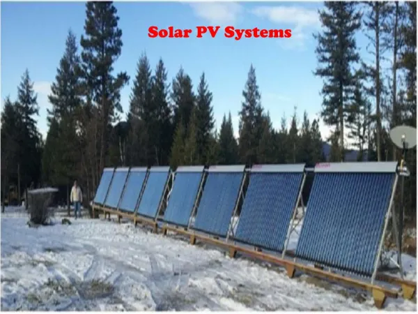
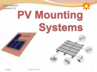
PV Mounting Systems
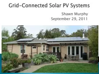
Grid-connect Session 7a. PV Mounting Systems. Grid-connect Session 3. The two main types of PV mounting systems; roof mounted and ground mounted. Ground mounted are used for massive ‘green field’ power station installations . Typically these systems generate 60-70 MWp. PV Mounting Systems.

PV Mounting Systems
E N D
Presentation Transcript
Grid-connectSession 7a PV Mounting Systems DAMON FYSON
Grid-connectSession 3 The two main types of PV mounting systems; roof mounted and ground mounted Ground mounted are used for massive ‘green field’ power station installations . Typically these systems generate 60-70 MWp PV Mounting Systems Roof mounted system are governed by many regulations, load bearing, wind loading, paramount; the PV modules are installed on fireproof material predominantly a tin or tiled roof DAMON FYSON
Grid-connectSession 3 AS/NZS 1170.2:2011 Australian/New Zealand Standard™ Structural design actions Part 2: Wind actions PV Mounting Systems SOURCE: http://www.civicsolar.com/resource/wind-load-calculations-solar-pv-arrays DAMON FYSON
Grid-connectSession 3 PV Mounting Systems AS/NZS 1170.2:2011 SCOPE This Standard sets out procedures for determining wind speeds and resulting wind actions to be used in the structural design of structures subjected to wind actions other than those caused by tornadoes. DAMON FYSON
Grid-connectSession 3 Today’s photovoltaic (PV) industry must rely on licensed structural engineers’ various interpretations of building codes and standards to design PV mounting systems that will withstand wind-induced loads. PV Mounting Systems SOURCE: http://www.civicsolar.com/resource/wind-load-calculations-solar-pv-arrays DAMON FYSON
Grid-connectSession 3 PV Mounting Systems Source: http://www.csiro.au/files/files/pis7.pdf DAMON FYSON
Grid-connectSession 3 Region A Most of Australia is designated Region A which indicates a Region Basic Wind Velocity of 41ms. PV Mounting Systems Region B Region B indicates a Region Basic Wind Velocity of 54ms. Local authorities will advise if this applies in the area. Region C Region C indicates a Region Basic Wind Velocity of 57ms and is generally refered to as cyclonic. These conditions are generally limited to norhtern coastal areas. Region D Region D (69ms) almost never occurs. Only use this if you know for sure it is what is required DAMON FYSON
Grid-connectSession 3 Install PV panels on a tin roof The following four slides illustrate the main steps PV Mounting Systems Web: www.powersmartsolar.com.au DAMON FYSON
Grid-connectSession 3 Install PV panels on a tin roof PV Mounting Systems Web: www.powersmartsolar.com.au DAMON FYSON
Grid-connectSession 3 Install PV panels on a tin roof PV Mounting Systems Web: www.powersmartsolar.com.au DAMON FYSON
Grid-connectSession 3 Install PV panels on a tin roof PV Mounting Systems Web: www.powersmartsolar.com.au DAMON FYSON
Grid-connectSession 3 Roof mounting systems allow solar modules to installed portrait or landscape orientation PV Mount orientationing Systems SOURCE renewableheatingcompany.co.uk Typical rectangular 24v modules 1600 x 800mm may be supported by two rails either across the long or short side. However many manufactures may only provide warranty for modules clamped on 1600mm side. Clamping on the 800mm side may not allow structural integrity of the module to withstand strong suction force caused by wind blowing over them, buckling may result with cracks in the glass DAMON FYSON
Grid-connectSession 3 Integrated Customers and architects may prefer the look of an installation where the solar modules become a integral part or the roof PV Mounting Systems Source:www.google.com.au/imgres?imgurl=http://www.enviora.com/blogs/media/blogs/enviora/sunrunpowertiles- DAMON FYSON
Grid-ConnectSession 3Grid-connectSession 3 Tiled roof Normal tiles require a tile hook that attaches flush to the rafters underneath the tiles, with a goose neck design having a protruding arm for attachment of rail mounting system • PV Mounting Systems Tile hook for lateral rail connectionSource:Creotecc - Roof Hook CREOFIX DAMON FYSON
Grid-connectSession 3 Non-Penetrating Roof Mount System Penetrations to roof structure that uses concealed fixings may void roof warranty on a ‘Klip-Loc’ roof these type on mounting bracket may be used. PV Mounting Systems Source: KlipKlamp Roof Mounts facebook.com DAMON FYSON
Grid-connectSession 3 PV Array Row Spacing On a flat roof, raking of the arrays may be an alternative solution to boost yield, however consideration must be given so that one row of modules does not cast a shadow on the row behind Note the shadow PV Mounting Systems DAMON FYSON
PV Array row spacing … ‘I need to quote on a PV system on a flat roof. ‘ The PV modules will be on tilted frames facing true North to optimise energy production How do I calculate the distance between PV Array rows to avoid winter mid-day shading ? Remembering back to high school math classes there was something called Trigonometry NOW YOU HAVE A USE FOR IT for any right angle triangle… if you know one angle and the length of any side you can calculate the length of the other two sides Grid-connectSession 3 PV Mounting Systems source: Clear Energy Council DAMON FYSON
Grid-connectSession 3 NOTE : This calculation gives the MINIMUM row spacing to avoid 10:00am to 2:00pm shading at the Winter solstice ( ~ June 22 ) PV Array row spacing … PV Mounting Systems SOURCE: Clear Energy Council 1. You know the length of the PV module - from the manufacturers data - and you have selected the optimum tilt angle. e.g. 1600mm and 30° 2. You then calculate height X e.g. Sin Tilt ° = X / 1600 … X = Sin 30° x 1600mm = 0.5 x 1600 = 800mm It is recommended that the row spacing avoids shading between 10:00am and 2:00pm at the Winter Solstice ( ~ June 22 ) refer to Table 1 on page 2. 3. the minimum spacing (Y) between rows can now be determined… Row spacing Y = X x Cos ( azimuth angle ) Tan ( altitude angle ) e.g. The PV array is located in SYDNEY - Latitude 34°S Azimuth = 31° and Altitude = 26° Y = X x Cos 31° / Tan 26° = 800mm x 1.757 = 1406 mm DAMON FYSON
Grid-connectSession 3 PV Array row spacing … PV Mounting Systems DAMON FYSON
How Solar Trackers Work Grid-connectSession 3 Solar trackers help maximize the sunlight absorption rate by minimizing the angle of incidence at which sunlight hits the solar panels. This in turn improves the conversion efficiency so the highest amount of power is generated from a fixed amount of sunlight during the day.The diagram shows how solar trackers can move photovoltaic panels horizontally and vertically in order to effectively utilize sunlight PV Mounting Systems (Image credit: www.solar-tracking.com) DAMON FYSON
Solar Trackers Work Grid-connectSession 3 PV Mounting Systems Source; http://rredc.nrel.gov/solar/calculators/PVWATTS/system.html PV array tilt angle (0° to 90°) For a fixed PV array, the tilt angle is the angle from horizontal of the inclination of the PV array (0° = horizontal, 90° = vertical). For a sun-tracking PV array with one axis of rotation, the tilt angle is the angle from horizontal of the inclination of the tracker axis. The tilt angle is not applicable for sun-tracking PV arrays with two axes of rotation. The default value is a tilt angle equal to the station's latitude. This normally maximizes annual energy production. Increasing the tilt angle favors energy production in the winter, while decreasing the tilt angle favors energy production in the summer DAMON FYSON
Grid-connectSession 3 Solar Trackers The Solar Tracker is a device capable of turning after the Sun, which means following the Sun’s track from its rising in the east to its setting in the west Because the Solar Tracker turns after the Sun all day long, the solar panels are set to face the Sun directly all day long, and so is their performance substantially enhanced. PV Mounting Systems DAMON FYSON
Grid-connectSession 3 PV Mounting Systems DAMON FYSON
Grid-connectSession 3 PV Mounting Systems http://rredc.nrel.gov/solar/calculators/PVWATTS/system.html great site for example of yield http://www.orer.gov.au/installers/index.html clear energy council DAMON FYSON