Quenching and Protection in Superconducting Magnets
310 likes | 365 Vues
Explore the quenching process, decay times, temperature rise, and quench protection schemes in superconducting magnets. Calculate resistance growth, heat dissipation, and current decay to ensure magnet safety. Learn about LHC quench protection and the implications of magnetic energy density.

Quenching and Protection in Superconducting Magnets
E N D
Presentation Transcript
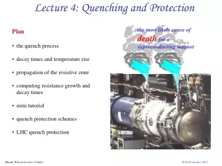
Lecture 4: Quenching and Protection the most likely cause of deathfor a superconducting magnet • Plan • the quench process • decay times and temperature rise • propagation of the resistive zone • computing resistance growth and decay times • mini tutorial • quench protection schemes • LHC quench protection JUAS February 2015
Magnetic stored energy at 5T E = 107 Joule.m-3 at 10T E = 4x10⁷ Joule.m-3 Magnetic energy density E = ½LI 2L = 0.12H I = 11.5kA E = 7.8 x 10⁶ Joules LHC dipole magnet (twin apertures) the magnet weighs 26 tonnes so the magnetic stored energy is equivalent to the kinetic energy of:- 26 tonnes travelling at 88km/hr coils weigh 830 kg equivalent to the kinetic energy of:- 830kg travelling at 495km/hr JUAS February 2015
The quench process • resistive region starts somewhere in the winding at a point- this is the problem! • it grows by thermal conduction • stored energy ½LI2of the magnet is dissipated as heat • greatest integrated heat dissipation is at point where the quench starts • maximum temperature may be calculated from the current decay time via the U(q) function (adiabatic approximation) • internal voltages much greater than terminal voltage ( = Vcs current supply) JUAS February 2015
The temperature rise function U(q) • Adiabatic approximation fuse blowing calculation • J(T) = overall current density, • T = time, • r(q) = overall resistivity, • = density q = temperature, • C(q) = specific heat, • TQ = quench decay time. • GSI 001 dipole winding is 50% copper, 22% NbTi, 16% Kapton and 3% stainless steel household fuse blows at 15A, area = 0.15mm2 J = 100Amm-2 NbTi in 5T Jc = 2500Amm-2 • NB always use overall current density JUAS February 2015
Measured current decay after a quench Dipole GSI001 measured at Brookhaven National Laboratory JUAS February 2015
Calculating temperature rise from the current decay curve U(q) (calculated) J 2 dt (measured) JUAS February 2015
Calculated temperature • calculate the U(q) function from known materials properties • measure the current decay profile • calculate the maximum temperature rise at the point where quench starts • we now know if the temperature rise is acceptable - but only after it has happened! • need to calculate current decay curve before quenching JUAS February 2015
Growth of the resistive zone the quench starts at a point and then grows in three dimensions via the combined effects of Joule heating and thermal conduction * JUAS February 2015
Quench propagation velocity 1 • resistive zone starts at a point and spreads outwards • the force driving it forward is the heat generation in the resistive zone, together with heat conduction along the wire • write the heat conduction equations with resistive power generation J 2r per unit volume in left hand region and r = 0 in right hand region. resistive v qt temperature superconducting qo xt distance where: k = thermal conductivity, A = area occupied by a single turn,g = density,C = specific heat,h = heat transfer coefficient,P = cooled perimeter, r= resistivity, qo = base temperature Note: all parameters are averaged over A the cross section occupied by one turn assume xt moves to the right at velocity v and take a new coordinatee = x-xt= x-vt JUAS February 2015
Quench propagation velocity 2 Jc rCu Jop reff qc qo qs qc qo qs qt when h = 0, the solution for q which gives a continuous join between left and right sides at qt gives the adiabatic propagation velocity recap Wiedemann Franz Law r(q).k(q) = Loq • what to say about qt ? • in a single superconductor it is just qc • but in a practical filamentary composite wire the current transfers progressively to the copper • current sharing temperature qs = qo + margin • zero current in copper below qs all current in copper above qc • take a mean transition temperature qt = (qs + qc )/2 JUAS February 2015
Quench propagation velocity 3 av av v the resistive zone also propagates sideways through the inter-turn insulation (much more slowly) calculation is similar and the velocity ratio a is: Typical values a = 0.01 - 0.03 vad = 5 - 20 ms-1 so the resistive zone advances in the form of an ellipsoid, with its long dimension along the wire Some corrections for a better approximation • because C varies so strongly with temperature, it is better to calculate an averaged C by numerical integration • heat diffuses slowly into the insulation, so its heat capacity should be excluded from the averaged heat capacity when calculating longitudinal velocity - but not transverse velocity • if the winding is porous to liquid helium (usual in accelerator magnets) need to include a time dependent heat transfer term • can approximate all the above, but for a really good answer must solve (numerically) the three dimensional heat diffusion equation or, even better, measure it! JUAS February 2015
Resistance growth and current decay - numerical vdt vdt avdt avdt * in time dt zone 1 grows v.dt longitudinally and a.v.dt transversely temperature of zone grows by dq1 =J2 r(q1)dt / g C(q1) resistivity of zone 1 isr(q1) calculate resistance and hence current decay dI = R / L.dt in time dt add zone n: v.dt longitudinal and a.v.dt transverse temperature of each zone grows by dq1 =J2r(q1)dt/gC(q1) dq2 =J2r(q2)dt/gC(q2) dqn=J2r(q1)dt /gC(qn) resistivity of each zone isr(q1) r(q2) r(qn) resistance r1= r(q1) * fg1(geom factor) r2= r(q2) * fg2rn= r(qn) * fgn calculate total resistance R = r1+ r2 +rn..and hence current decay dI = (IR/L)dt when I 0 stop start resistive zone 1 JUAS February 2015
Quench starts in the pole region * * * * * * the geometry factor fg depends on where the quench starts in relation to the coil boundaries JUAS February 2015
Quench starts in the mid plane * * * JUAS February 2015
Computer simulation of quench (dipole GSI001) pole block 2nd block mid block JUAS February 2015
OPERA: a more accurate approach solve the non-linear heat diffusion & power dissipation equations for the whole magnet JUAS February 2015
Compare with measurement • can include • ac losses • flux flow resistance • cooling • contact between coil sections but it does need a lot of computing Coupled transient thermal and electromagnetic finite element simulation of Quench in superconducting magnets C Aird et al Proc ICAP 2006 available at www.jacow.org JUAS February 2015
Mini Tutorial: U(q) function It is often useful to talk about a magnet quench decay time, defined by: i) For the example of magnet GSI001, given in Lecture 4, Td = 0.167 sec Use the U(qm) plot below to calculate the maximum temperature. ii) This was a short prototype magnet. Supposing we make a full length magnet and compute Td = 0.23 sec. - should we be worried? iii) If we install quench back heaters which reduce the decay time to 0.1 sec, what will the maximum temperature rise be? Data Magnet current Io = 7886 Amps Unit cell area of one cable Au = 13.6 mm2 JUAS February 2015
U(qm ) function for dipole GSI001 JUAS February 2015
Methods of quench protection: 1) external dump resistor • detect the quench electronically • open an external circuit breaker • force the current to decay with a time constant where • calculate qmax from Note: circuit breaker must be able to open at full current against a voltage V = I.Rp (expensive) JUAS February 2015
Methods of quench protection: 2) quench back heater • detect the quench electronically • power a heater in good thermal contact with the winding • this quenches other regions of the magnet, effectively forcing the normal zone to grow more rapidly higher resistance shorter decay time lower temperature rise at the hot spot spreads inductive energy over most of winding Note: usually pulse the heater by a capacitor, the high voltages involved raise a conflict between:- - good themal contact - good electrical insulation method most commonly used in accelerator magnets JUAS February 2015
Methods of quench protection: 3) quench detection (a) I internal voltage after quench V t • not much happens in the early stages - small dI/dt small V • but important to act soon if we are to reduce TQ significantly • so must detect small voltage • superconducting magnets have large inductance large voltages during charging • detector must reject V = LdI/dt and pick up V = IR • detector must also withstand high voltage -as must the insulation JUAS February 2015
Methods of quench protection: 3) quench detection (b) i) Mutual inductance • ii) Balanced potentiometer • adjust for balance when not quenched • unbalance of resistive zone seen as voltage across detector D • if you worry about symmetrical quenches connect a second detector at a different point D detector subtracts voltages to give • adjust detector to effectively make L = M • M can be a toroid linking the current supply bus, but must be linear - no iron! JUAS February 2015
Methods of quench protection: 4) Subdivision • resistor chain across magnet - cold in cryostat • current from rest of magnet can by-pass the resistive section • effective inductance of the quenched section is reduced reduced decay time • reduced temperature rise • current in rest of magnet increased by mutual inductance • quench initiation in other regions • often use cold diodes to avoid shunting magnet when charging it • diodes only conduct (forwards) when voltage rises to quench levels • connect diodes 'back to back' so they can conduct (above threshold) in either direction JUAS February 2015
Inter-connections can also quench photo CERN any part of the inductive circuit is at risk • coils are usually connected by superconducting links • joints are often clamped between copper blocks • link quenches but copper blocks stop the quench propagating • inductive energy dumped in the link • current leads can overheat JUAS February 2015
LHC dipole protection: practical implementation • It's difficult! - the main challenges are: • 1) Series connection of many magnets • In each octant, 154 dipoles are connected in series. If one magnet quenches, the combined energy of the others will be dumped in that magnet vaporization! • Solution 1: cold diodes across the terminals of each magnet. Diodes normally block magnets track accurately. If a magnet quenches, it's diodes conduct octant current by-passes. • Solution 2: open a circuit breaker onto a resistor (several tonnes) so that octant energy is dumped in ~ 100 secs. • 2) High current density, high stored energy and long length • Individual magnets may burn out even when quenching alone. • Solution 3: Quench heaters on top and bottom halves of every magnet. JUAS February 2015
LHC power supply circuit for one octant circuit breaker • in normal operation, diodes block magnets track accurately • if a magnet quenches, diodes allow the octant current to by-pass • circuit breaker reduces to octant current to zero with a time constant of 100 sec • initial voltage across breaker = 2000V • stored energy of the octant = 1.33GJ JUAS February 2015
LHC quench-back heaters • stainless steel foil 15mm x 25 mm glued to outer surface of winding • insulated by Kapton • pulsed by capacitor 2 x 3.3 mF at 400 V = 500 J • quench delay - at rated current = 30msec - at 60% of rated current = 50msec • copper plated 'stripes' to reduce resistance JUAS February 2015
Diodes to by-pass the main ring current Installing the cold diode package on the end of an LHC dipole JUAS February 2015
Quenching: concluding remarks always do quench calculations before testing magnet • magnets store large amounts of energy - during a quench this energy gets dumped in the winding intense heating (J ~ fuse blowing) possible death of magnet • temperature rise and internal voltage can be calculated from the current decay time • computer modelling of the quench process gives an estimate of decay time – but must decide where the quench starts • if temperature rise is too much, must use a protection scheme • active quench protection schemes use quench heaters or an external circuit breaker - need a quench detection circuit which rejects LdI/dt and is 100% reliable • passive quench protection schemes are less effective because V grows so slowly at first - but are 100% reliable • don’t forget the inter-connections and current leads JUAS February 2015