Advanced Performance Testing of CCUM Rods and Optohybrids at CMS Tracker Week 2003
230 likes | 352 Vues
The presentation details the extensive testing of CCUM integrated systems and optohybrids within the CMS Tracker framework during April 2003. Highlighted are the advancements from a new FEC to CCUM adapter and updates in noise assessment for improved data acquisition (DAQ) performance. The setup included high-speed readout and calibration enhancements to address previously encountered low-frequency trigger issues. Furthermore, noise characterization and signal integrity were evaluated using cosmic muons and radioactive sources, demonstrating excellent detector behaviors and alignment methods for future experiments.

Advanced Performance Testing of CCUM Rods and Optohybrids at CMS Tracker Week 2003
E N D
Presentation Transcript
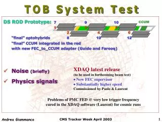
CCUM 7 9 10 1 3 5 2 4 6 8 10 12 TOB System Test • DS ROD Prototype: • “final” optohybrids • “final” CCUM integrated in the rod • with new FEC_to_CCUM adapter (Guido and Farooq) • Noise (briefly) • Physics signals XDAQ latest release (to be used in forthcoming beam test) New FEC supervisor Substantially higher speed Commissioned by Paolo & Laurent Problems of PMC FED @ very low trigger frequency cured in the XDAQ software (Laurent) for cosmic runs CMS Tracker Week April 2003
The ROD test setup See previous talks at the last tracker and cms weeks ! Alu box, gas tight, with patch panel for pipes (C6F14 cooling and dry air) and other services (it can house 2 rods) Modules, optohybrids, CCUM, high voltage Daq PC with 1 TSC, 1 FEC and 3 FED cards, DAQ Software CMS Tracker Week April 2003
Basic tuning procedure of DAQ settingswell established in XDAQ discussed in previous system test presentations (Paolo) • Standard APV settings • Time alignment in the FED • PLL scan • Optimization of laser bias and gain [N.B. Isha=80 Vpsp=30 inverting mode] (24 and 2, with non individual tuning) Detailed study of noise & correlated noise as for SS rod repeated for all modules Excellent behaviour • low common mode • flat noise distribution CMS Tracker Week April 2003
CCUM 7 9 10 1 3 5 2 4 6 8 10 12 8 2 FNAL modules old ceramic hybrid - DCU2 Noise studied in all modules… pedi=<ADCi>ev tot: RMS of ADCi-pedi 7 d: RMS of 0.5(ADCi-ADCi+1) 1 nrm: RMS of ADCi-pedi-CMN0 lin: RMS of ADCi-pedi-CMNi CMN0 = <ADCi-pedi>strip CMNi = b+a i a = CM Slope CMS Tracker Week April 2003
106Ru61(Q=3.5 MeV) Trigger rate ~500 Hz Study of physics signals Cosmics TSC gate = 6 ns Low voltage Hamamatsu PM Trigger rate ~0.5 Hz Well assessed delay scan to find signal (Laurent) Analysis: tools developed by Roberto, Paolo, Andrea CMS Tracker Week April 2003
Cluster finding Very simple cluster definition: S/N • S/N > 2 for every strip in a cluster • S/N > 5 for the highest signal strip cluster not a cluster (“seed”) 5 Signal: sum of the signals of the strips Noise: noise of the seed 2 strips No special treatment for bad strips CMS Tracker Week April 2003
Physics signals - b source Source on the center of a sensor Deconvolution mode / inverter ON Det #1 S/N=21.2 CMS Tracker Week April 2003
Physics signals - b sourcepeak mode inverter ON Det #1 S/N=33.3 CMS Tracker Week April 2003
tot: RMS of ADCi-pedi Det #7 d: RMS of 0.5(ADCi-ADCi+1) nrm: RMS of ADCi-pedi-CMN0 lin: RMS of ADCi-pedi-CMNi missing bond (S1-S2) CMN0 = <ADCi-pedi>strip CMNi = b+a i a = CM Slope missing bond (PA) Partial signal recovery from neighbours: Group of missing and shorted bonds CMS Tracker Week April 2003
Physics signals - Cosmics Deconvolution mode / inverter ON Det #1 S/N=25.6 ~20% higher than b rays CMS Tracker Week April 2003
Time delay scan Nclusters/Ntriggers vs delay Det #7 Nclusters/Ntriggers=95.5% @ t=0 Not the detector efficiency! • noise of scintillator • spurious triggers (not ideal collimator) Use only events seen by the other detector: eupper=Nupper&lower/Nlower=99.9% elower=Nupper&lower/Nupper=99.8% CMS Tracker Week April 2003
Source on the bonding normalized to same area Source on the center Source on the bonding Det #7 Nclusters/Ntriggers=79.3% @ t=0 subtracting Evidence for region with lower charge collection efficiency near the edge CMS Tracker Week April 2003
7 1 CCUM 7 9 10 1 3 5 2 4 6 8 10 12 2 8 Source on the overlap x axis CMS Tracker Week April 2003
CCUM 7 9 10 1 3 5 2 4 6 8 10 12 Alignment x axis 7-1: 1.2+-0.1 strips 7-8: 1.5+-0.7 strips 2-8: 0.5+-0.2 strips (220+-18 mm) (91+-36 mm) (275+-128 mm) Rod alignment pins were not integrated! CMS Tracker Week April 2003
CCUM 7 9 10 1 3 5 2 4 6 8 10 12 “Tracking” with 2 hits Slope of the line passing through the hits in 7&1 vs Position on 7 m=tg q 7 3 mm q 1 x position of the source Deviations from linearity due to the finite size of the source CMS Tracker Week April 2003
CCUM 7 9 10 1 3 5 2 4 6 8 10 12 “Tracking” with 4 hits x axis m=tg q Slope of the best fit line for the hits in 7&1 &2 &8 vs Position on 7 7 x position of the source 3 mm 1 8 mm q 2 3 mm 8 x axis CMS Tracker Week April 2003
Conclusions • Fully equipped DS rod thoroughly tested • also with physics signals: no problem found. • Analysis of physics signals provides a complementary view of detector defects. • Simple method to qualify rod geometry commissioned. • Calibration of 106Ru61vs high energy cosmic muons performed 106Ru61: Cosmics: deco: peak: S/N=21 S/N=33 S/N=25 If muons (@ 500 mm) = 40000 electrons noise (@ deco) = 1600 electrons identical to predictions. CMS Tracker Week April 2003
Electrons vs capacitance CMS Tracker Week April 2003
Noise: module #7 FNAL module - old ceramic hybrid - DCU2 (deconvolution) pedi=<ADCi>ev tot: RMS of ADCi-pedi d: RMS of 0.5(ADCi-ADCi+1) nrm: RMS of ADCi-pedi-CMN0 lin: RMS of ADCi-pedi-CMNi CMN0 = <ADCi-pedi>strip CMNi = b+a i a = CM Slope • To be compared with performance on physics signals CMS Tracker Week April 2003
Noise: module #1 FNAL module - old ceramic hybrid - DCU2 (deconvolution) pedi=<ADCi>ev tot: RMS of ADCi-pedi d: RMS of 0.5(ADCi-ADCi+1) nrm: RMS of ADCi-pedi-CMN0 lin: RMS of ADCi-pedi-CMNi CMN0 = <ADCi-pedi>strip CMNi = b+a i a = CM Slope • To be compared with performance on physics signals CMS Tracker Week April 2003
Noise: module #8 FNAL module - old ceramic hybrid - DCU2 (deconvolution) pedi=<ADCi>ev tot: RMS of ADCi-pedi d: RMS of 0.5(ADCi-ADCi+1) nrm: RMS of ADCi-pedi-CMN0 lin: RMS of ADCi-pedi-CMNi CMN0 = <ADCi-pedi>strip CMNi = b+a i a = CM Slope • To be compared with performance on physics signals CMS Tracker Week April 2003
Noise: module #2 FNAL module - old ceramic hybrid - DCU2 (deconvolution) pedi=<ADCi>ev tot: RMS of ADCi-pedi d: RMS of 0.5(ADCi-ADCi+1) nrm: RMS of ADCi-pedi-CMN0 lin: RMS of ADCi-pedi-CMNi CMN0 = <ADCi-pedi>strip CMNi = b+a i a = CM Slope • To be compared with performance on physics signals CMS Tracker Week April 2003
ADCi-pedi-CMN0 ADCi-pedi-CMNi CMN0 = <ADCi-pedi>strip CMNi = b+a i a = CM Slope Det #7 kurtosis Non gaussian noise! CMS Tracker Week April 2003