Wireless
Infrastructure Wireless :: base station network is connected to the wired Internet. Ad hoc Wireless :: wireless nodes communicate directly with one another. ...

Wireless
E N D
Presentation Transcript
Slide 1:Wireless Local Area Networks from Tanenbaum�s �Computer Networks�, Fourth Edition
Slide 2:Wireless Local Area Networks
The proliferation of laptop computers and other mobile devices (PDAs and cell phones) created an obvious application level demand for wireless local area networking. Companies jumped in, quickly developing incompatible wireless products in the 1990�s. Industry decided to entrust standardization to the IEEE committee that dealt with wired LANS � namely, the IEEE 802 committee!!
Slide 3:IEEE 802 Standards Working Groups
Figure 1-38. The important ones are marked with *. The ones marked with ? are hibernating. The one marked with � gave up.
Slide 4:Wireless Network Categories
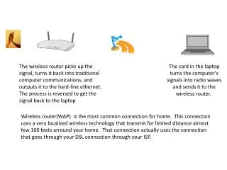
Base Station :: all communication through an access point {note hub topology}. Other nodes can be fixed or mobile. Infrastructure Wireless :: base station network is connected to the wired Internet. Ad hoc Wireless :: wireless nodes communicate directly with one another. MANETs (Mobile Ad Hoc Networks) :: ad hoc nodes are mobile.
Slide 5:Wireless LANs
Figure 1-36.(a) Wireless networking with a base station. (b) Ad hoc networking.
Slide 6:The 802.11 Protocol Stack
Note � ordinary 802.11 products are no longer being manufactured. Figure 4-25. Part of the 802.11 protocol stack.
Slide 7:Wireless Physical Layer
Physical layer conforms to OSI (five options) 1997: 802.11 infrared, FHSS, DHSS 1999: 802.11a OFDM and 802.11b HR-DSSS 2001: 802.11g OFDM 802.11 Infrared Two capacities 1 Mbps or 2 Mbps. Range is 10 to 20 meters and cannot penetrate walls. Does not work outdoors. 802.11 FHSS (Frequence Hopping Spread Spectrum) The main issue is multipath fading. 79 non-overlapping channels, each 1 Mhz wide at low end of 2.4 GHz ISM band. Same pseudo-random number generator used by all stations. Dwell time: min. time on channel before hopping (400msec).
Slide 8:Wireless Physical Layer
802.11 DSSS (Direct Sequence Spread Spectrum) Spreads signal over entire spectrum using pseudo-random sequence (similar to CDMA see Tanenbaum sec. 2.6.2). Each bit transmitted using an 11 chips Barker sequence, PSK at 1Mbaud. 1 or 2 Mbps. 802.11a OFDM (Orthogonal Frequency Divisional Multiplexing) Compatible with European HiperLan2. 54Mbps in wider 5.5 GHz band ? transmission range is limited. Uses 52 FDM channels (48 for data; 4 for synchronization). Encoding is complex ( PSM up to 18 Mbps and QAM above this capacity). E.g., at 54Mbps 216 data bits encoded into into 288-bit symbols. More difficulty penetrating walls.
Slide 9:Wireless Physical Layer
802.11b HR-DSSS (High Rate Direct Sequence Spread Spectrum) 11a and 11b shows a split in the standards committee. 11b approved and hit the market before 11a. Up to 11 Mbps in 2.4 GHz band using 11 million chips/sec. Note in this bandwidth all these protocols have to deal with interference from microwave ovens, cordless phones and garage door openers. Range is 7 times greater than 11a. 11b and 11a are incompatible!!
Slide 10:Wireless Physical Layer
802.11g OFDM(Orthogonal Frequency Division Multiplexing) An attempt to combine the best of both 802.11a and 802.11b. Supports bandwidths up to 54 Mbps. Uses 2.4 GHz frequency for greater range. Is backward compatible with 802.11b.
Slide 11:802.11 MAC Sublayer Protocol
In 802.11 wireless LANs, �seizing the channel� does not exist as in 802.3 wired Ethernet. Two additional problems: Hidden Terminal Problem Exposed Station Problem To deal with these two problems 802.11 supports two modes of operation DCF (Distributed Coordination Function) and PCF (Point Coordination Function). All implementations must support DCF, but PCF is optional.
Slide 12:Figure 4-26.(a)The hidden station problem. (b) The exposed station problem.
Slide 13:The Hidden Terminal Problem
Wireless stations have transmission ranges and not all stations are within radio range of each other. Simple CSMA will not work! C transmits to B. If A �senses� the channel, it will not hear C�s transmission and falsely conclude that A can begin a transmission to B.
Slide 14:The Exposed Station Problem
This is the inverse problem. B wants to send to C and listens to the channel. When B hears A�s transmission, B falsely assumes that it cannot send to C.
Slide 15:Distribute Coordination Function (DCF)
Uses CSMA/ CA (CSMA with Collision Avoidance). Uses both physical and virtual carrier sensing. Two methods are supported: based on MACAW(Multiple Access with Collision Avoidance for Wireless) with virtual carrier sensing. 1-persistent physical carrier sensing.
Slide 16:Wireless LAN Protocols
MACA protocol solved hidden, exposed terminal: Send Ready-to-Send (RTS) and Clear-to-Send (CTS) first RTS, CTS helps determine who else is in range or busy (Collision avoidance). Can a collision still occur? Note � RTS/CTS is optional! When the frame size is small, WLANs may not use RTS/CTS. Professor Agu�s slide
Slide 17:Wireless LAN Protocols
(a) A sending an RTS to B.(b) B responding with a CTS to A. MACAW added ACKs and CSMA (no RTS at same time) Professor Agu�s slide
Slide 18:Virtual Channel Sensing in CSMA/CA
Figure 4-27. The use of virtual channel sensing using CSMA/CA. C (in range of A) receives the RTS and based on information in RTS creates a virtual channel busy NAV(Network Allocation Vector). D (in range of B) receives the CTS and creates a shorter NAV.
Slide 19:Virtual Channel Sensing in CSMA/CA
What is the advantage of RTS/CTS? RTS is 20 bytes, and CTS is 14 bytes. MPDU can be 2300 bytes. �virtual� implies source station sets duration field in data frame or in RTS and CTS frames. Stations then adjust their NAV accordingly!
Slide 20:Figure 4-28. Fragmentation in 802.11
High wireless error rates ? long packets have less probability of being successfully transmitted. Solution: MAC layer fragmentation with stop-and-wait protocol on the fragments.
Slide 21:1-Persistent Physical Carrier Sensing
Station senses the channel when it wants to send. If idle, station transmits. Station does not sense channel while transmitting. If the channel is busy, station defers until idle and then transmits. Upon collision, wait a random time using binary exponential backoff.
Slide 22:Point Coordinated Function (PCF)
PCF uses a base station to poll other stations to see if they have frames to send. No collisions occur. Base station sends beacon frame periodically. Base station can tell another station to sleep to save on batteries and base stations holds frames for sleeping station.
Slide 23:DCF and PCF Co-Existence
Distributed and centralized control can co-exist using InterFrame Spacing. SIFS (Short IFS) :: is the time waited between packets in an ongoing dialog (RTS,CTS,data, ACK, next frame) PIFS (PCF IFS) :: when no SIFS response, base station can issue beacon or poll. DIFS (DCF IFS) :: when no PIFS, any station can attempt to acquire the channel. EIFS (Extended IFS) :: lowest priority interval used to report bad or unknown frame.
Slide 24: Figure 4-29. Interframe Spacing in 802.11