Download
1 / 31
330 likes | 487 Vues
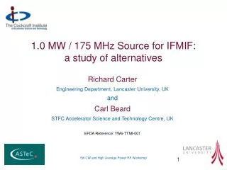
1.0 MW / 175 MHz Source for IFMIF: a study of alternatives. Richard Carter Engineering Department, Lancaster University, UK and Carl Beard STFC Accelerator Science and Technology Centre, UK EFDA Reference: TW6-TTMI-001. Overview. IFMIF RF System Conceptual design of an IOT

E N D
1.0 MW / 175 MHz Source for IFMIF:a study of alternatives Richard Carter Engineering Department, Lancaster University, UK and Carl Beard STFC Accelerator Science and Technology Centre, UK EFDA Reference: TW6-TTMI-001 5th CW and High Average Power RF Workshop
Overview • IFMIF RF System • Conceptual design of an IOT • Conceptual design of a magnetron • Conclusions 5th CW and High Average Power RF Workshop
Overview • IFMIF RF System • Conceptual design of an IOT • Conceptual design of a magnetron • Conclusions 5th CW and High Average Power RF Workshop
The International Fusion Materials Irradiation Facility Accelerator reference design [1] • Two CW 175 MHz linear accelerators • 125 mA, 40 MeV deuteron beam. • Conventional, room-temperature, RF linac 5th CW and High Average Power RF Workshop
IFMIF RF power system conceptual design 5th CW and High Average Power RF Workshop
IFMIF Power Requirements 5th CW and High Average Power RF Workshop
Baseline RF Power Source 1000 Hours operation demonstrated with 98.7% availability 5th CW and High Average Power RF Workshop
Overview • IFMIF RF System • Conceptual design of an IOT • Conceptual design of a magnetron • Conclusions 5th CW and High Average Power RF Workshop
Inductive Output Tube (IOT) • Grid-modulated like a tetrode • Operated in class AB or B for high efficiency • All electrons have full EHT energy • Compared with a tetrode • Lower current • Higher voltage • Higher gain 5th CW and High Average Power RF Workshop
Inductive Output Tube (IOT) 5th CW and High Average Power RF Workshop
IOT State of the Art Pf 2 = constant 5th CW and High Average Power RF Workshop
Conceptual Design of 175 MHz / 1.0 MW IOT • PRF = 1.0 MW; f = 175 MHz • Assume efficiency: η = 65% • PDC = 1.0 / 0.65 = 1.54 MW • Assume peak current (Class B) • Ipk = 3.6 I0 • Assume peak perveance Ipk/V3/2 = 2 × 10⁻⁶ • Ipk = 58A I0 = 16.2A V0 = 95 kV • Assume peak cathode loading 1 A/cm2 • Cathode radius: rc = 43 mm 5th CW and High Average Power RF Workshop
Conceptual Design of 175 MHz / 1.0 MW IOT • Electron velocity: • u0 = 1.6 × 10⁸ m.sec-1 • Electronic propagation constant: • βe = ω/u0 = 6.9 m-1 • Choose normalised beam radius: βeb = 0.06 • b = 8.6 mm • Drift tube radius: a = 1.5 × b = 13mm • Area convergence: (rc / b)2 = 25:1 • Brillouin field: BB = 0.045T 5th CW and High Average Power RF Workshop
Conceptual Design of 175 MHz / 1.0 MW IOT • Typical gridded gun parameters • Grid transparency: 80% • Grid wire radius: 0.5 mm • Grid pitch: 5 mm • Amplification factor: 200 • Grid voltage at cut-off: Vg0 = -475V 5th CW and High Average Power RF Workshop
Conceptual Design of 175 MHz / 1.0 MW IOT • RF performance • Fundamental RF beam current: I1 = 0.5 × Ipk = 29A • RF grid voltage: Vg1 = 475 V • RF input power: Pin = 0.5 × Vg1 × I1 = 6.9kW • Gain: 21.6dB 5th CW and High Average Power RF Workshop
Overview • IFMIF RF System • Conceptual design of an IOT • Conceptual design of a magnetron • Conclusions 5th CW and High Average Power RF Workshop
CW Magnetrons 5th CW and High Average Power RF Workshop
CW Magnetron State of the Art Pf 2 = constant 5th CW and High Average Power RF Workshop
CW Magnetron Efficiency 5th CW and High Average Power RF Workshop
Injection Locking ω0magnetron frequency without injection ωi injected frequency QLrefers to the loaded magnetron. [7] For a typical magnetron Pinj is about 10 dB below PRF 5th CW and High Average Power RF Workshop
Magnetron Frequency Pushing • Frequency depends on the anode current • Switched-mode power supply in a phase-locked loop stabilises the frequency by controlling the current [8], [9] 5th CW and High Average Power RF Workshop
Accurate control of a ‘cooker’ magnetron • Frequency is stabilised with a phase-locked loop • Injection locking is then possible with much lower injected power • Phase locked to better than 1º with injected power – 37dB • 90º PSK modulation demonstrated at 2 MHz • Magnetron responds to 90º phase shift in ~200 nsec • It might be possible to use controlled magnetrons to power an accelerator 5th CW and High Average Power RF Workshop
Conceptual Design of 175 MHz / 1.0 MW Magnetron • PRF = 1.0 MW; f = 175 MHz • Assume efficiency: η = 85% • PDC = 1.0 / 0.65 = 1.2 MW • Assume impedance V0/I0 = 3.0 kΩ • V0 = 60 kV I0 = 20A • Use a high normalised magnetic field to achieve the target efficiency 5th CW and High Average Power RF Workshop
Conceptual Design of 175 MHz / 1.0 MW Magnetron Design criteria: • Cathode loading < 1.0 A/cm2 • Cathode height << λ0 • Anode vane tip temperature < 600 K • Product EVa < 1000 kV2/mm 5th CW and High Average Power RF Workshop
Conceptual Design of 175 MHz / 1.0 MW Magnetron 5th CW and High Average Power RF Workshop
Conceptual Design of 175 MHz / 1.0 MW Magnetron 5th CW and High Average Power RF Workshop
Overview • IFMIF RF System • Conceptual design of an IOT • Conceptual design of a magnetron • Conclusions 5th CW and High Average Power RF Workshop
Comparison of Sources 5th CW and High Average Power RF Workshop
IOT Development • Possible with current technology • Would require 2 - 3 years R&D • Issues • Mechanical stability of control grid • Multi-element depressed collector design • Demonstration of life and reliability 5th CW and High Average Power RF Workshop
Magnetron development • Appears to be possible • Would require 4 – 5 years R&D • Issues • Cathode choice for long life • Development of switched mode power supply • Demonstration of simultaneous control of amplitude and phase stability • Demonstration of lifetime and reliability 5th CW and High Average Power RF Workshop
References • IFMIF Comprehensive Design Report (2004) • http://www.cpii.com/product.cfm • H. Bohlen, E. Davies, P. Krzeminski, Y.li and R. Tornoe, “Inductive output tubes for particle accelerators”, EPAC 2004, pp.1111-3 • http://www.caltubelab.com/products/cwm.html • e2v technologies plc • C. Shibata, “High power (500-kW) CW magnetron for industrial heating”, Elect. Engg. Japan, Vol.111, pp.94-101 (1991) • R. Adler, “A study of locking phenomena in oscillators”, Proc.IEEE Vol.61, pp.1380-83 (1973) • I. Tahir, A. Dexter and R Carter, “Noise performance of frequency- and phase-locked CW magnetrons operated as current-controlled oscillators”, IEEE Transactions on Electron Devices Vol. 52,pp.2096- 2103 (2005) • I. Tahir, A. Dexter and R Carter, “Frequency and phase modulation performance of an injection-locked CW magnetron” IEEE Transactions on Electron Devices Vol. 53, pp.1721-29 (2006) 5th CW and High Average Power RF Workshop


![[f´‚nE˘RIks]](https://cdn0.slideserve.com/1072532/f-ne-riks-dt.jpg)


![[f´‚nE˘RIks]](https://cdn2.slideserve.com/5310017/f-ne-riks-dt.jpg)