Download
1 / 20
200 likes | 225 Vues
Learn about the updated Design Margin in long-term gas transmission planning and its role in ensuring safety, security, and system reliability. Discover the components and review outcomes influencing this vital aspect.

E N D
Transmission Planning Code – Design Margin Update Transmission Workstream, 4th February 2010
Introduction • National Grid NTS has revised the Design Margin used in long term planning analysis following a review by Advantica (now GL Industrial Services UK Ltd.) • Intention is to consult on the required changes to the Transmission Planning Code in February 2010 • Following slides describe the Design Margin and how it is used, to supplement the consultation process
Design Margin – Brief Overview (1) • National Grid NTS must be able to maintain sufficient pressure for gas leaving the NTS, to ensure safety and security of supplies to downstream parties (DNOs, directly connected customers) • Planning and development of the system is undertaken over a ten year timescale but must consider uncertainties present ahead of and within the gas flow day such as • NTS supply levels, flow profiles, distribution and supply availability • NTS demand levels, flow profiles and distribution • Plant availability • Design Margin is applied as a % uplift to forecast flows within long term planning analysis to account for uncertainties or unplanned events • Key assumption is that Operating Margins gas is available within 2 hours of the event occurring and will be used to support the system from this time onwards
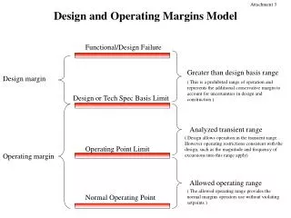
Design Margin – Brief Overview (2) • Design Margin in use since 1986, reviewed in 2000 and 2008 • Level of design margin required is calculated through statistical modelling of within day events and network analysis to verify proposed design margin • Applied automatically within planning software to increase the flows used within network models • Effect is to slightly exaggerate the pressure drops across the system • Provides a small degree of pressure cover across the system for a limited time until Operating Margins gas can be deployed • If system is constrained, or only just meets required pressure and flow obligations, introducing a Design Margin may signal that a reinforcement is required
Design Margin Review 2008 • National Grid NTS recently commissioned a review from Advantica to consider • Previous flow margin studies undertaken in 1986 and 2000 • Statistical analysis of within day variations over a 2 year period • Network modelling to confirm level of design margin required • Rationale behind the design margin and the operating margin, and whether these could overlap • Main conclusion was transmission component no longer required due to • Development of contractual/market-based commercial regime • Increased use of supply and demand scenarios to understand sensitivity away from Base Case flows • Additional pressure cover at system extremities was recommended • Study confirmed that the design margin and operating margin are used for different purposes and therefore do not overlap
Transmission Component • Typical lead-times for NTS investment projects are 3-4 years from inception • Peak day supply and demand forecasts may change in this period • NTS must be maintained to the 1-in-20 peak day security standard and to ensure gas is delivered at the required pressures to downstream parties • Transmission component intended to counteract annual plan changes due to • Geographical redistribution of supply between entry points and demand between exit points • Demand variation due to changes in economic assumptions • Supply level variations • Uncertainty in model pipe efficiency parameters • Original requirement for transmission component driven by uncertainty around central case planning assumptions • Increased use of scenario planning has reduced the requirement to model uncertainty by use of a fixed uplift factor
Transient Component • Long-term planning analysis is conducted assuming 100% plant availability including upstream infrastructure • Plant failures and supply outages may occur in reality • Daily balancing regime means that instantaneous/cumulative NTS supply and demand levels are often not balanced within day • Total supplies may lag behind demand especially if back-loading is present • Linepack (NTS gas stock) may be depleted in some areas and increased in other areas as a result • Transient component allows for within-day effects (and is still required) • LDZ demand forecast error • Offshore supply outages leading to temporary reductions in supply • Supply (re)nominations requiring NTS reconfigurations • Compressor trips
DesignMargin - prior to 2008 review • Varies from 0-5% depending on type of analysis undertaken
Design Margin – recommendations from 2008 review • Review concluded Transmission component not required due to • Development of contractual/market-based commercial regime • Increased scenario analysis to understand sensitivities around TBE Base Case flows • Additional pressure cover for sensitive geographic locations required
Pressure Cover • Use of a Design Margin inherently provides pressure cover for operational circumstances as pressure drops are slightly exaggerated in long term planning analysis • Extremities of the system may still be sensitive to unplanned plant failures e.g. where they are immediately downstream of a compressor station • Additional pressure cover can be calculated by simulating the compressor trip at different times during the gas day to determine • The pressure cover implied by the Design Margin • The pressure decay immediately after the compressor trip, up to two hours after the trip • Additional pressure cover is applied as an increment to the Assured Offtake Pressures at the extremity to ensure minimum pressures are not breached within two hours of the compressor trip • Two system extremity points are currently considered
Transmission Planning Code • National Grid NTS has a licence obligation to maintain a Transmission Planning Code to describe how it undertakes the planning and development of the network • Current version available at: http://www.nationalgrid.com/uk/Gas/TYS/TPC/ • During development of the planning code, National Grid discussed its intention to revise the value of the Design Margin used within its long term planning models • Presentations available on Joint Office website (TPC Workshop 3 on 5 June 2008) • Design Margin revised from 5% to 2% following a review by Advantica (GL) in 2008 • Design Margin described with National Grid’s Safety Case for the NTS and therefore required discussion with the HSE before modification
Transmission Planning Code – Required Updates • Modifications to Safety Case are now complete and National Grid will be launching a consultation in February 2010 to update the Transmission Planning Code as required by its NTS Licence • Further consultations are planned in 2010 to reflect changes in the Exit regime and Planning legislation • Please contact Chandima Dutton on 01926 653231 or chandima.dutton@uk.ngrid.com if you wish to discuss any aspects of the Transmission Planning Code • Design Margin will be kept under review • Design Margin value will be stated in Transmission Planning Code rather than the Safety Case • Changes will still require discussion with HSE
Example: Design Margin impact after a compressor trip Compressor 1 Supply A Demand C Supply B Compressor 2 Operating Margins gas in store, availability within 2 hours • Example assumes that only one supply/demand scenario used for long term planning • In reality various sensitivities around the TBE Base are considered to ensure that a range of flow patterns and flow levels are modelled • Explicit modelling of sensitivities and obligations reduces level of design margin required
Long Term Planning Case 1: No Design Margin appliedSystem meets min pressure requirements design flow = 40 mscmd Supply A Demand C supply pressure = 70 bar(g) min pressure = 40 bar(g) Supply B modelled pressure = 40 bar(g) design flow = 60 mscmd • Pressure drop calculated across system = 30 bar(g) • Min pressure at Demand C just satisfied • Long term planning analysis identifies no reinforcement requirement
Operations Case 1: No Design Margin appliedWithin-day compressor trip flow = 40 mscmd Supply A Demand C supply pressure = 70 bar(g) min pressure = 40 bar(g) Supply B system pressure = 40 bar(g) before trip decays rapidly after trip flow = 60 mscmd • Compressor trip causes extremity pressure to fall below min pressure before operating margins gas can be brought online Operating Margins gas in store, 2 hours availability
Long Term Planning Case 2: Design Margin applied e.g.5% used in planning analysis design flow = 40 x 1.05 mscmd Supply A Demand C supply pressure = 70 bar(g) min pressure = 40 bar(g) Supply B modelled pressure = 38.5 bar(g) design flow = 60 x 1.05 mscmd • Pressure drop calculated across system = 31.5 bar(g) • Min pressure at Demand C not satisfied • Long term planning analysis identifies that reinforcement is required
Long Term Planning Case 2: Design Margin appliedSystem reinforced to meet min pressure requirements design flow = 40 x 1.05 mscmd Supply A Demand C min pressure = 40 bar(g) Supply B modelled pressure = 40 bar(g) design flow = 60 x 1.05 mscmd • Pressure drop across system = 30 bar(g) after reinforcement • System meets required pressure at extremity • Pressure cover of 1.5 bar(g) at Demand C has been provided by Design Margin for operational use Reinforcement
Operations Case 2: Design Margin appliedWithin-day compressor trip flow = 40 mscmd Supply A Demand C min pressure = 40 bar(g) Supply B system pressure = 41.5 bar(g) before trip and decays rapidly after trip flow = 60 mscmd • Extremity pressure affected by compressor trip, however pressure cover of 1.5 bar(g) is used to absorb impact of trip for two hours • After 2 hours, Operating Margins gas assumed to be available Operating Margins gas in store, 2 hours availability