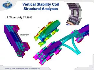
A300 VERTICAL TAIL STRUCTURAL EVALUATION
A300 VERTICAL TAIL STRUCTURAL EVALUATION. DESIGN FLAW IN LOWER REAR SPAR By Xavier J. Maumus. A300 VERTICAL TAIL STRUCTURAL EVALUATION. DESIGN FLAW IN LOWER REAR SPAR PART 1—DESIGN FLAW DETAILS PART 2--FAILSAFE CRITERIA PART 3--ULTIMATE CRITERIA PART 4—FAILURE SCENARIO.

A300 VERTICAL TAIL STRUCTURAL EVALUATION
E N D
Presentation Transcript
A300 VERTICAL TAIL STRUCTURAL EVALUATION DESIGN FLAW IN LOWER REAR SPAR By Xavier J. Maumus
A300 VERTICAL TAIL STRUCTURAL EVALUATION DESIGN FLAW IN LOWER REAR SPAR PART 1—DESIGN FLAW DETAILS PART 2--FAILSAFE CRITERIA PART 3--ULTIMATE CRITERIA PART 4—FAILURE SCENARIO
A300 VERTICAL TAIL STRUCTURAL EVALUATION PART 1—DESIGN FLAW DETAILS
Spar Design Susceptible to Lateral Deflection Spar and Yoke Reaction System Designed Primarily to React Lateral Load. Relieves Lateral Shear and Bending in the Main Lugs. Geometry makes Yoke Design Very Efficient in Resisting Lateral Deflection. Poor in Resisting Vertical Deflection. . CRITICAL DESIGN FEATURE Rear Reaction System
NTSB Docket No. 168606, Factual Report 02-077, pg 9 of 63, Section 2.2.2 Suspected Description of a Bearing Failure in LHS Rear Transverse Spar Lug Located at the Upper/Outboard Edge of the Lug Bore. This Failure Produced Substantial Compression in the LH Yoke which is Inconsistent with the FEM Boundary Loads. Working Model Demonstrates that the Lower Rear Spar moves to the Right which is necessary to Produce Compression Load in the LH Yoke. DISCOVERY OF FLAW
MECHANICAL LEVER Lever Bar Py Vertical Tail Rotation of Lever Bar Develops Resistance Ps Main Lug Reaction 0 Yoke Reaction
Geometry of Lower Rear Spar Design Produces a Mechanical Lever (ML) in the Spar Reaction System. As Aft Portion of the VT Deflects, its Lower SparRotates and Produces Lateral Deflection at Spar Attachment to the Yokes. Spar Reaction System is Very Efficient in Developing Lateral Resistance. Yokes Resist and Develop Large Internal Loads in VT Reaction System. Loads are Reacted at the Main Lugs (Shear and Out-of Plane Bending) and Additive to the VT Loads. DESIGN FLAW
Py ROTATION OF NO 1 RIB AND REAR SPAR .480 in. Deflection of Lug Fulcrum Rotation of Spar Produces Large Deflections at Yokes REAR REACTION SYSTEM FAILSAFE CONFIGURATION S P
LOAD DEVELOPMENT IN LEVER MECHANISM • Spar Rotates and Produces Lateral Deflections at its Lug Attachment to the Yokes • Yokes Resist Lateral Deflection and Develop Large Internal Loads in Reaction System • Large Shear and Bending Loads are Reacted at the Rear Main Lugs
Vertical Movement of Failed RHS Main Lug Fulcrum—Located near Rib No. 1 in Skin Transition Area above LHS Lug .480 in Transverse Spar Rotates Counterclockwise about Fulcrum 0 Resistance to Spar Deflection Develop Large Loads in Yokes MECHANICAL LEVERAGE FAILSAFE CONFIGURATION Additional Side Load Reacted at LHS Main Lug
For Failsafe Criteria with the RHS Rear Main Lug Disconnected, the FEM shows the RHS Lug moves to the Right and Up. Deflections Consistent with the Mechanical Leverage Model, Shows Rotation of Spar. Most Significant is the Deflection to the Right which Verifies the Spar’s tendency to move Laterally. This Lateral Movement is what Produces the Interference Resistance Between the Spar and Yoke. Working Model Demonstrates the Flaw. Loads and Deflection Analysis Results are Consistent when Mechanical Leveraging is Consisted. EVIDENCE OF DESIGN FLAW
3.70 S MXX P FREEBODY OF LUGAdditional Load on Lug Bore Lateral Resistance in Yokes Produce Additional Shear and Bending in Lug
Mechanical Leveraging makes the Design Susceptible to small Deflections in the Lower Spar Structure. Large Internal Loads are Produced in all members of the VT Reaction Systems, Main Lugs are especially Susceptible. Airbus FEM does not Account for Mechanical Leverage in the Loads Analysis. FEM Deflections are Correct. Mechanical Leverage supports a Pre-mature Failure in the RHS Rear Main Lug below Ultimate Renders Failsafe Capability Ineffective SIGNIFICANCE OF ML
TEST TO PROVE DESIGN FLAW Full Scale Test Failsafe Criteria RHS Rear Main Lug Released Apply Load 25% Limit BI 17 TEST CASE VS. AIRBUS FEM Note the large load in the RHS Yoke for Test Case Vertical Tail and Rudder mounted on Aircraft
TEST TO PROVE DESIGN FLAW Full Scale Test Ultimate Criteria Apply Load 25% Limit BI 17 TEST CASE VS. AIRBUS FEM Note the difference in sign between the two load cases Vertical Tail and Rudder mounted on Aircraft
TEST TO PROVE DESIGN FLAW Perform Full Scale Calibration Test of Vertical Tail on A300 Aircraft • Disconnect Fairings, Control Rods and Systems to Avoid Damage to A/C • Mount Cameras to Record Movement of Rear Spar • Strain Gauge and Calibrate Aft Yokes • Apply Side Load (12,000 lb about 25% Limit Load) to VT about 157 Inches Above Attachment • Read Gauges and Measure Rotational Deflection of Rear Spar • Disconnect RHS Rear Main Lug and Repeat Test
The Effectiveness of the Mechanical Lever is Dependent on the Location of the Fulcrum, how was this Point Located? In the Failsafe Analysis, the Fulcrum is located near the Intersection of the LH Skin and N0. 1 Rib. The Fulcrum location is a Function of the Stiffness of Two Primary Structural Members. One is the VT Box that is very Stiff and whose Lower Side is Bound by the No. 1 Rib. The other being the LH Main Lug Area whose Stiffness is a Function of its Moment of Inertia and Fixity at the Lug Attachment. These Stiffness Parameters Produce a Natural Inflection Point 2.83 inches above the Main Lug Bore. In the Ultimate Criteria Analysis, no Fulcrum Location is Determined. A .0125 inch Lateral Displacement is Assumed since no FEM Defection Data is Available for Ultimate. Questions
PHYSICAL EVIDENCESupports Mechanical Leverage • Bearing Failure in LHS Aft Transverse Spar Lug Located at the Upper/Outboard Edge of the Lug Bore. NTSB Docket No. 168606, Factual Report 02-077, pg 9 of 63, Section 2.2.2. The Bearing Failure indicates that the Lower Spar moved to the right to Produce this Failure. Deformation of Left Transverse Yoke Sleeve. NTSB Docket No. 168606, page 5 of 63.
A300 VERTICAL TAIL STRUCTURAL EVALUATION PART 2--FAILSAFE CRITERIA DESIGN FLAW IN TRANSVERSE SPAR
FAILSAFE CRITERIA • Requires That Vertical Tail Structure Sustain Limit Load With One Major Structural Member Failed
AIRBUS FAILSAFE PHILOSOHY • When one of the Main Lugs Fail, the Loads of that Lug are Redistributed, Primarily to an Adjacent Main Lug • In the Case of a Failure in the RHS Rear Main Lug, 90% of the Load goes Forward and only 10% is Resisted by the Yokes • In Order for this Redistribution to Occur the Design must Allow the Failed Lug to Deflect
AIRBUS FAILSAFE ANALYSIS Assumes RHS Rear Main Lug Fails • Results Based on Non-Linear FEM Analysis—Set for Strain Solution • Design Certification Lateral Gust Condition at Limit Load • LHS Spar Lug Critical • Max Deflection of the Right Rear Main Lug in A/C Coordinates is: x = .004 in., y = .037 in and z = .480 in.
AIRBUS FEM RESULTSNon-Linear Analysis FAILURE ANALYSIS—RHS REAR MAIN LUG FAILSAFE—BI17 LIMIT LOAD (LB)
3.54 1.224 Dia. PLUG = 32,742 lb. LHS 1.574 3.54 1.224 DIA. 1.547 AIRBUS DETAIL ANALYSIS LHS SPAR LUG CRITICAL Load Capacity of Lug = 40,271 lb. Ulti. Margin of Safety = + .23 Limit Critical for Shear Tear Out
MECHANICAL LEVERAGE FAILSAFE ANALYSISAssumes Right Rear Main Lug Fails • Results Based on Deflection Analysis (Virtual Work) • Considers Mechanical Leverage in Lower Spar • Design Certification Lateral Gust Condition at Limit Load • Deflection of the Right Rear Main Lug in A/C Coordinates is: y = .037 z = .480 in.
Py ROTATION OF NO 1 RIB AND REAR SPAR .480 in. Deflection of Lug Fulcrum Rotation of Spar Produces Large Deflections at Yokes REAR REACTION SYSTEM FAILSAFE CONFIGURATION S P
LOADS ANALYSISAnalysis Considers Mechanical Leverage FAILURE ANALYSIS—RHS REAR MAIN LUG FAILSAFE—BI17 LIMIT LOAD
DETAIL STRESS ANALYSIS RHS SPAR LUG CRITICAL 3.54 3.54 Load Capacity of Lug = 40,271 lb. Ulti. Margin of Safety = - .24 Limit Critical for Shear Tear Out 1.224 Dia. 1.224 DIA. PLUG = 52,811 lb. RHS 1.547 1.574
TRANSITION AREAINTER-LAMINA SHEAR CRITICAL 20.00 PINTER-LAMINA SHEAR = 79724 lb. Inter-lamina Shear Capacity = 50,215 lb. Ulti. Margin of Safety = - .37 Limit 1.17 SECTION A-A A A UP FWD LOOKING INB’D LHS REAR MAIN LUG
CONCLUSIONSBased on Analysis Considering Mechanical Leverage • RHS Rear Spar Lug will Fail at 76% of Limit Load • LHS Rear Main Lug will Fail at 63% of Limit Load • Vertical Tail does not Meet Failsafe Criteria when Considering Mechanical Leverage
The Component Tests were Used to Support Failsafe Certification. Why didn’t this Flaw Show Up During those Tests? To my Knowledge none of the Spar Component Tests Included Yokes attached to the Spar, so the Additional Internal Loads from Mechanical Leverage wasn’t Allowed to Develop. Additionally, Component Testing never Examined a Failsafe Condition in which a Main Lug was disconnected. The Boundary Loads used in all Component Tests were Controlled by the FEM Loads Analysis that did not Account for Mechanical Leverage. Question
A300 VERTICAL TAIL STRUCTURAL EVALUATION PART 3--ULTIMATE CRITERIA ANALYSIS IS INCOMPLETE NEED DEFLECTION DATA OF REAR SPAR
ULTIMATE CRITERIA • Requires That Vertical Tail Structure Sustain 1.5 Times Limit Load Without Failure of any Major Structural Member
AIRBUS ANALYSIS--ULTIMATE • Results Based on Non-Linear FEM Analysis—Set for Strain Solution • Design Certification Lateral Gust Condition at Ultimate Load • RHS Rear Main Lug Critical
S MXX P RHS Lug View looking Aft AIRBUS FEM RESULTSNon-linear Analysis BI17 LOAD CASE—ULT. S = 3,100 LB P = 160,319 LB MXX = 41,109 IN-LB Margin of Safety = +.18 Critical for Shear Tear Out
Py Py Fulcrum S S 0 Pc Pt REAR REACTION SYSTEM NORMAL CONFIGURATION Rotation of Spar Produces Deflections at Yokes
MECHANICAL LEVERAGE Mechanical Leverage Influences the Distribution of Internal Load in Rear Reaction System Fulcrum—Located near Rib No. 1 Additional Side Load Reacted at RHS Main Lug Additional Side Load Reacted at LHS Main Lug 0 Rear Spar Rotates Counterclockwise Produces Deflection at Lugs Resistance to Spar Lateral Deflection at Lugs are Developed in Yokes
S MXX P DETAIL ANALYSIS RESULTS Considers Mechanical Leverage BI17 LOAD CASE—ULT. NO DEFLECTION DATA AVAILABLE, ASSUMES LATERAL INTERFERENCE IN YOKES = .0125 IN. (.030 Vertical Deflection of Rear Spar) S = 26,075 LB P = 160,319 LB MXX = 74,376 IN-LB Margin of Safety = - .13 Critical for Shear Tear Out RHS Lug View Looking Aft
CONCLUSIONSBased on Analysis Considering ML • Assume Lateral Deflection of .0125 in. in Rear Spar --Need Deflection Data-- • Rear Main Lugs will Fail at 87% of Ultimate Load • Must be Substantiated by FEM Analysis and Full Scale Static Test on Aircraft • Vertical Tail may not Meet Ultimate Criteria
The Full Scale Static Test was Used to Support Ultimate Certification. The Test Article Failed at 126 % of Ultimate. Why didn’t this Flaw Show Up During this Test? The Full Scale Static Test didn’t Include Yokes, so the Additional Internal Bending Load in the Rear Main Lugs from Mechanical Leverage wasn’t Allowed to Develop. The Boundary Loads of the Static Test were a Duplication of the FEM Loads Analysis that did not Account for Mechanical Leverage. . Questions
RECOMMENDATIONFEM ANALYSIS • Current Airbus FEM Internal Loads Analysis needs Modification to Account for Mechanical Leverage of Rear Spar • FEM should be run on Non-linear set for Geometry Solution
RECOMMENDATIONNTSB • Perform Proof Test • Full Scale Tests to Failure should be Preformed for both Failsafe and Ultimate Criteria
A300 VERTICAL TAIL STRUCTURAL EVALUATION PART 4—FAILURE SCENARIO QUESTIONS
FAILURE SCENARIO The RHS Rear Main Lug Failed First at below Limit and Initiated a Series of Failures in the Rear Attachment System. • RHS Rear Main Lug Weakened by Overload Event 7 Years Earlier--Second Wake Encounter • LHS Rear Main Lug--Thump • Rear Transverse Spar Lugs, RHS then LHS --Two Thumps • Rib No. 1 between Middle and Rear Spar– Snap and Loud Thump • Fwd and Middle Main Lugs and Yokes Instantaneously– Loud Bang
What Caused the RHS Rear Main Lug to Fail? There is no way of knowing the exact Strength of the failed RHS Main Lug, but in Part 3 of this Presentation, Ultimate Analysis shows that the Lug might not meet Design Strength Requirements when Mechanical Leverage is Considered. The Lug had been Weakened by an Overload Event that Occurred Seven Years Earlier. During this Event the Lug came very Close to Failure and Caused Delamination around the Lug Bore. Increase Stress from the Mechanical Leverage Phenomena caused further Delamination and Weakening of the Damaged Lug Continued Until Failure. Questions
How does Mechanical Leverage support Pre-mature Failure of the RHS Rear Main Lug? Bending Loads in the Lug are reacted at the Lug Bore and Produce Strain in the Critical Outer Fibers of the Lug. Mechanical Leverage Increases these Bending Strains making the Lug even more Susceptible to Delamination. If the Lug has been Damaged from a Previous Overload Event, it is even more Susceptible to further Delamination. As the Lug Continues to Weaken from Delamination, the Bending Strains in its Outer Fibers are Driven to Larger Levers Promoting Delamination Growth. QUESTIONS
Why do you believe the RHS Rear Lug Failed below Limit? My Analysis supports a Failure Scenario in which the RHS Rear Main Lug may have been severely damaged from the Overload Event that the Aircraft Experienced Seven Years earlier. The Mechanical Leverage Effect Develops larger than expected Bending Loads in the Lug that caused further Delamination Growth. Over the Years, the Lug continuously Weakens until it Pre-maturely Fails (below Limit Load) when Exposed to the Loads of the Second Jet Wake Encounter about 17 Seconds before Separation. Questions
What Proof Exist to Support a Failure of the RHS Rear Main Lug below Limit? No Direct Evidence Exist to show that the Lug Failed below Limit. Failure Scenario Assumes that the Lug Ruptured at Second Wake Encounter. Wake Encounter Load seems Less than Limit. Need Analysis supported by Testing. (Yes, you can say that Failsafe did not work but remember that Airbus will say that it was a load beyond Limit that caused the VT to go at once. You need some evidence that there was no overload or that the intact system is not capable of carrying the load.) Questions
What Evidence Exist to Support a Zipper Type Failure of the VT? This Presentation provides Physical Evidence and Failsafe Analysis that Supports a Series of Failures (below Limit) in the Rear Attachment System that may have Lasted a number of seconds. The Physical Evidence suggests a Series of Component Failures that is Consistent with a Zipper Type Failure and takes some Time to Develop because the Loading is not Overwhelming. The Mechanical Leverage Design Flaw and Delamination Damage of the other AA Aircraft proves a problem exist with the Design. Cockpit Voice Recording suggest that something was happening to the Aircraft 17 seconds before the VT Departure. Questions
What does the Voice Recording Suggest to you? Its an indication that the Vertical Tail may have been coming apart at least 17 seconds before separation from the aircraft. During the time between 0915:51.8 and 0915:58.5, there are recorded the sounds of three thumps, one snap, one loud thump and one loud bang. These sounds were probably the sounds of the VT's aft reaction system failing and No. 1 Rib breaking apart with the last 'loud bang' at 0915:58.5 being the sound of the simultaneous failure of the fwd and middle structure. Questions