Download
1 / 38
650 likes | 1.29k Vues
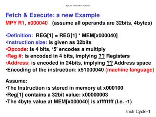
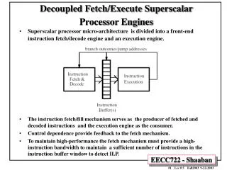
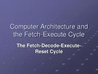
Computer Architecture and the Fetch-Execute Cycle. The Fetch-Decode-Execute-Reset Cycle. Learning Objectives. Describe in simple terms the fetch / decode / execute / reset cycle and the effects of the stages of the cycle on specific registers. The Fetch-Decode-Execute-Reset Cycle.

E N D
Computer Architecture and the Fetch-Execute Cycle The Fetch-Decode-Execute-Reset Cycle
Learning Objectives • Describe in simple terms the fetch / decode / execute / reset cycle and the effects of the stages of the cycle on specific registers.
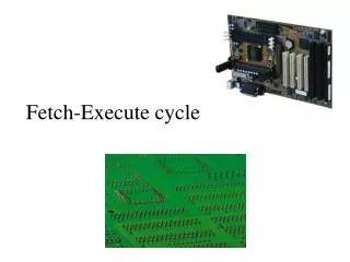
The Fetch-Decode-Execute-Reset Cycle • The following is an algorithm in diagrammatic form that shows the steps in the cycle. • It is the control unit which controls and synchronises this cycle. • Loads / copies / places / passes, decodes and executes. • At the end the cycle is reset and the algorithm repeated.
Key for following slides: • PC / SQR • Program Counter / Sequence Control Register • MAR • Memory Address Register • MDR / MBR • Memory Data Register / Memory Buffer Register • CIR • Current Instruction Register • ACC • Accumulator
Idle Registers • Note that during the Fetch - Decode – Execute - Reset cycle demonstrated on the following slides, some registers are idle (not being used). • This will be discussed and resolved in the next lesson.
ACC ALU Memory Fetch CPU PC incremented by 1 Copy of instruction in memory address held in MAR Copy of address of next instruction PC MAR CIR Instruction MDR Control Unit
ACC ALU Decode CPU MAR PC Split instruction into operation code & address if present. Then decode operation code. CIR MDR Control Unit
ACC ALU Execute CPU MAR PC Execute instruction (What is involved in this depends on the instruction being executed - demonstrated on the following slides). CIR MDR Control Unit
Click an instruction or move on to see each instruction in turn. Jump Input / Load (number directly) Input / Load (from memory) Add (a number directly) Add (a number from memory) Store Output (directly from accumulator) Output (from memory)
Jump instruction Execute Diagram
ACC ALU Execute CPU Jump MAR PC Copy of address part instruction (address to jump to). CIR MDR Control Unit
ACC ALU Execute CPU Jump Copy of address part instruction (address to jump to). PC MAR CIR MDR Control Unit Back to list of instructions
Input / Load (number directly) into accumulator instruction Execute Diagram
Execute Input / Load (number directly) into accumulator CPU MAR PC Number inputted / to be loaded. CIR MDR Control Unit Copy of number in MDR. ACC ALU Back to list of instructions
Reason for the CIR & MDR • As you can see the MDR is used to store the number inputted / to be loaded during the execution of this Input / Load instruction. • Therefore, if there was no CIR to hold the Input / Load instruction and, as no register can hold more than one “thing” at a time, the control unit would “lose” the Input / Load instruction. • i.e. It would no longer “know” what it was supposed to do. • You will find that the contents of the MDR may be modified for similar reasons during other later instructions. Back to list of instructions
Load (from memory) instruction Execute Diagram
Execute Memory CPU Load (from memory) Copy of data in address held in MAR MAR PC Address part of instruction (of data to be loaded). CIR MDR Control Unit Copy of data in MDR ACC ALU Back to list of instructions
Reason for the PC & MAR • As you can see the MAR is now used to store the address part of instruction during the execution of this Load (from memory) instruction. • Therefore if there was no MAR the PC would be used to hold this address so the control unit would no longer know the correct address of the next instruction. • You will find that the contents of the MAR may be modified for similar reasons during other later instructions. Back to list of instructions
Add (a number directly) instruction Execute Diagram Assume a number has already been inputted or loaded (directly or from memory) into the accumulator.
Execute Add (a number directly) CPU PC MAR CIR Number to be added. MDR Control Unit Add number in MDR to number already in accumulator. ACC ALU NB. The ALU now does the arithmetic. Accumulator value is now the result of the addition. i.e. Accumulator = Accumulator + contents of MDR Back to list of instructions
Add (a number from memory) instruction Execute Diagram (Assume a number has already been inputted or loaded into the accumulator.)
Execute Memory CPU Add (from memory) Control Unit Control Unit Copy of number in memory address held in MAR PC MAR CIR Address part of instruction (of number to add). MDR Add number in MDR to number already in accumulator. ACC ALU NB. The ALU now does the arithmetic. Accumulator value is now the result of the addition. i.e. Accumulator = Accumulator + contents of MDR Back to list of instructions
Store instruction Execute Diagram Assume data has either been inputted, loaded (directly or from memory) or a calculation has been performed. Any of the above will mean there is data in the accumulator and it is this data that will be stored.
Execute Memory CPU Store Control Unit Copy of data in MDR stored in memory address held in MAR PC MAR Address part of instruction (to store in). CIR MDR Copy of data in accumulator ACC ALU Back to list of instructions
Output (directly from accumulator) instruction Execute Diagram
Execute Output (directly from accumulator) CPU PC MAR CIR Output data in accumulator MDR Control Unit ACC ALU Back to list of instructions
Output (from memory) instruction Execute Diagram
Execute Memory Output (from memory) CPU Copy of data in memory address held in MAR Control Unit MAR PC Address part of instruction (of data to output). CIR MDR Output data in accumulator Copy of data in memory address held in MAR ACC ALU Back to list of instructions
Reset CPU PC Cycle is reset (restarted) by passing control back to the PC.
The CIR changes: • When an instruction is loaded into it from the MDR. • When the address in the instruction in the CIR is modified by the addition of the contents of an Index register (IR): • A previously unmentioned register which is covered in more detail in the next Special Registers and Memory Addressing Techniques Presentation.
Idle Registers • Note that during the Fetch - Decode – Execute - Reset cycle demonstrated on the previous slides, some registers were idle (not being used). • This will be discussed and resolved in the next lesson.
Fetch – Decode - Execute – Reset Cycle in writing • The following slides describe the cycle in writing.
Load the address of next instruction in the PC into the MAR. • So that the control unit can fetch the instruction from the right part of the memory. • Copy the instruction/data that is in the memory address given by the MAR into the MDR. • MDR is used whenever anything is to go from the CPU to main memory, or vice versa. • Increment the PC by 1. • So that it contains the address of the next instruction, assuming that the instructions are in consecutive locations. • Load the instruction/data that is now in the MDR into the CIR. • Thus the next instruction is copied from memory -> MDR -> CIR. • Contents of CIR split into operation code and address if present e.g. store, add or jump instructions. • Decode the instruction that is in the CIR. Fetch Decode
Execute the instruction but what is involved in this depends on the instruction being executed (there are several different instructions you need to know about). • If the instruction is a jump instruction then • Load the address part of the instruction in the CIR into the PC. • If the instruction is an input / load (directly) instruction then take data input and place in accumulator. • If the instruction is a load (from memory) instruction. • Copy address part of the instruction (to load from) in the CIR into MAR. • Copy data from memory address held in MAR to MDR. • Copy data in MDR into accumulator. Execute
If the instruction is a store instruction then: • Copy address part of the instruction (to store in) in the CIR into MAR. • Copy data in accumulator to MDR. • Copy data in MDR into memory address held in MAR. • If the instruction is an add instruction then: • Copy address part of the instruction (of number to add) in the CIR into MAR. • Copy number from memory address held in MAR into MDR. • Add number in MDR to number in accumulator (accumulator will now hold the result). • If the instruction is an output (directly from accumulator) then output number in accumulator. Execute
Execute • If the instruction is an output (from memory) instruction then: • Copy address part of part of the instruction (of data to output) in CIR into MAR. • Output contents of MDR. • Cycle is reset (restarted) by passing control back to the PC (step 1). Reset
Plenary • Describe the fetch / decode part of the fetch / decode / execute / reset cycle, explaining the purpose of any special registers that you have mentioned.
Plenary • Contents of PC loaded into MAR • PC is incremented • Contents of address stored in MAR loaded into MDR • Contents of MDR loaded into CIR • Instruction in CIR is decoded. • PC (program counter) stores the address of the next instruction to be executed. • MAR (memory address register) holds the address in memory that is currently being used • MDR (memory data register) holds the data (or instruction) that is being stored in the address accessed by the MAR. • CIR (current instruction register) holds the instruction which is currently being executed.