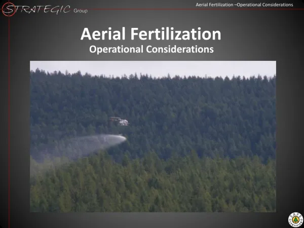
Operational considerations
Operational considerations. Reported by B.Goddard CERN TE/ABT The work described is that of many colleagues, in particular M.Aiba , J.Borburgh , C.Carli , M.Chanel , A.Fowler , M.Martini , W.Weterings. Outline. Transverse painting and kicker system Beam losses

Operational considerations
E N D
Presentation Transcript
Operational considerations Reported by B.Goddard CERN TE/ABT The work described is that of many colleagues, in particular M.Aiba, J.Borburgh, C.Carli, M.Chanel, A.Fowler, M.Martini, W.Weterings
Outline • Transverse painting and kicker system • Beam losses • Injection optimisation and matching • Stripping foil • Foil temperatures • Failure cases • Injection chicane issues • Maintenance concerns • Instrumentation
Transverse painting • Painting round linac beam of enx/y0.4 um • LHC beam aiming for enx/y= 2 um (immediately after injection) • High intensity (CNGS, FT, ...) beam aiming for enx/y10/4 um • Injection over 20 - 80 PSB turns (1 us per turn) • Design of distributer allows up to 100 turns • Horizontal painting with closed 4-bump • Linear fall.... • Reusing existing KSW magnets • Modification of 1 KSW position • No vertical painting (at present) – fixed offset
Painting and chicane bump timing tinj(20/80 turns) tKSW(80-120 turns) tBS(few 1000 turns) KSW (painting) BS (chicane) 1/e Exp! Inj start Inj end
Painting kicker locations and strengths Present chicane + painting bump (27 mm as in published TDR) Move KSW magnet from injection straight to start of period 16 (rebuild to standardise) Preferred version (space, strengths) Present magnets/power supplies are sufficient for 35 mm bump at 160 MeV Increasing beyond 35 mm requires minor upgrade of 1L4 and 2L1 systems – easily possible
Machine aperture for 27/35 mm bumps 27mm painting bump 35mm painting bump Aperture adequate (from simple envelopes) (Chicane bump off for clarity) Painting kickers
Machine aperture with chicane MB QF MB QF BS4 / H0 dump BS1 Start of painting Painting bump off
Vertical painting? • No vertical painting forseen • Injection with ~2mm fixed offset and some betatron mismatch to give ~ 2 mm emittance for LHC beam • For CNGS beam aiming for 3-4 mm vertically • Options to overcome this include: • Mismatch injection more? Means different line optics for different beams... • Increase fixed offset? Would start to give hollow beam distribution.... • Rely on blow-up from space-charge effects? Maybe not controlled enough... • Needs more detailed investigations with ORBIT to see which option is preferred
Beam losses at machine apertures • 35 mm painting bump OK for machine aperture • Chicane bump amplitude is 45 mm • Foil edge is at about 74 mm…. • Aperture limit in machine similar at many elements • MBs, QFs, Painting kicker 1L1 • Aperture limits in injection region • at H0 dump inside BS4 – needs optimisedshape • At BS1 septum no worse than elsewhere • Still needs quantification with numerical simulations during injection process and for early part of ramp • Some ingredients exist • Particle distributions from Linac4 (from 2006) • ORBIT model of PSB including proposed injection elements • Madx aperture model of PSB (needs to be updated) • Long/trans painting schemes and parameters • First basic tests have been made with ORBIT but now need expanding in scope
Injection optimisation and matching • Optimisations and detailed evaluations made with linear tracking, ACSIM and ORBIT • Need painting bump fall times around 80-120 turns for LHC/CNGS beams • Investigations of injection mismatch, especially Dx/Dpx from transfer line • No strong effects on emittance growth seen on dispersion mismatch • Presently assuming zero Dx/Dpx at delivery point • H emittance blow-up from this of about 0.5 mm (free painting) M.Aiba, C.Carli, B.Goddard, M.Martini,
ORBIT simulation results with space-charge for LHC beam M.Aiba
Foil hits for different dispersion matches • Longitudinal painting has big impact (±0.4% dp/p plus momentum spread and jitter....) • Zero dispersion means some injection mismatch • Foil hits remain low, around 5/p+ • Matched dispersion beam moves, larger foil (15 30 mm) • Can increases foil hits from 5/p+ to about 15/p+ • Prefer zero dispersion at delivery point • keep option open for matched value if possible (line optics) Fixed foil width (30 mm) Foil size matched (30 – 15 mm)
Choice of foil thickness / material • Assume C foil (several types possible) • Stripping efficiency calculated from extrapolated cross-section data Assume 200 ug/cm2 as reasonable thickness (H0 yield at about 0.1%) i.e. between 1 and 2 mm thick. Small compared to 2% assumed to miss foil....(btw is this realistic?)
Beam loss from scattering • Initial estimates: particles undergoing elastic or inelastic scattering lost, while MC scattering increases emittance • Use nuclear interaction length ll to estimate fraction of p+ lost • Ns/N0 = 1 - exp(-L/ll) • ll0.3 m • Single passage of 2 mm foil gives 7x10⁻⁶ loss per proton hit • Losses at few 1e-4 level for 5-15 hits/p+ expected
Emittance increase from foil scattering • Calculated analytically from RMS angle increase Up to around 20 foil hits/p+ looks acceptable (effect worse in H plane due to larger b)
Foil temperatures • Estimates using p+ density maps from linear tracking • Use non-linear C heat capacity to derive DT • Results cross-checked with ORBIT (new module by M.Aiba) • Very moderate for normal operation • As expected from the relatively low number of turns LHC beam (20 turns) – 85 K CNGS beam (80 turns) – 240 K
Foil temperatures & cooling • Thermal cycling also evaluated for different foil thicknesses • DT of 120 (LHC) to 360 K (CNGS) per injection (pessimistic assumptions on intensity) • Basic thermal and full ANSYS models for injection at 2 Hz (also pessimistic) • Cycling at 2 Hz adds 20 K for LHC, 100 K for CNGS beam (with 10 um foil!) Hottest point 1 umfoil Foil corner 10 umfoil W.Weterings, M.Aiba
Foil shape / orientation • Simulations to date have assumed foil supported on 3 sides (most pessimistic for heating and hits/p+) • Not realistic as needs very large foil • Presently assume foil supported on 2 sides only • Supporting on 1 edge may not be necessary – although smaller foil may be advantage mechanically • Technical investigations of materials and supports to be made – rely heavily on experience from other labs • Also suggestion (M.Chanel) to incline foil at 45 to investigate
Injection failure cases • Faults can happen with distributer, septum, painting kickers and steering elements • Worst cases are associated with fast kickers: • Distributer failure • 4 x 100 turns injected into one ring • Painting bump (& chicane) triggering failure • 80 turns in one ring with no painting
Injection failures – painting bump decay not triggered • With 80 turns of injected beam, already looks bad • Beam emittance stays very small (1 mm) • In this case foil reaches 3000 K within 350 turns (0.35 ms) • Chicane decay not assumed to trigger – but in any case with slow decay (3000 turns) does not help much • Looks dangerous - link distributer triggering to painting bump triggering? Some interlocking needed....
Injection failure – 400 turns in one ring • Assume painting bump decay triggered correctly • Otherwise reduces to previous case…with 5x more beam injected • Maximum foil temperatures up to 2000 K if the chicane is not triggered (1700 K if it is triggered) • Can mitigate against this scenario...HW system for distributer triggering probably easiest and most reliable place to ensure maximum 100 ms of beam per ring Chicane decay not triggered Chicane decay triggered
Other failure cases • Foil failure with full beam (100 ms) on H0 dump • Thermal load per injection is relatively low (around 700 J) • Instantaneous temperature rise <10 K for 100 cm3 C dump block – only apparent possible issue might be thermal shock in any local cooling channels • Needs nuclear and thermal design for verification • Would be factor 4 worse for combined distributer/foil failure... • First impressions is that it does not seem to be a problem provided not left in this condition for many repeated shots • Need for surveillance and interlocking system to cut linac beam
Stripping foil lifetime • Expected foil temperatures do not look too threatening • Normal operation – remain at about 600 K • Failure cases – can reach 2000 K for distributer failure, and failure to trigger painting bump may destroy the foil • Foil damage from elastic scattering • With low beam power and low energy, expected to be well above 104 hours from theory – not an issue.... • Experience from other labs • Poor foils can fail quickly (hours) • Good foils can last for weeks or months • In PSB case also have 4 rings to run....cannot afford to stop once per month per ring • Aim to run for 1 year without exchanging foil module • Need foil exchange system with 10 (?) foils plus screen...(5 foils seems feasible - see W.Weterings talk) • Again need input from other labs on operational experience
Other beam losses during injection • Excited H0 production and fringe field stripping loss mechanism also considered analytically • Principal quantum states with n=5 and above are field-stripped in BS3 fringe • Pessimistically assume all this is lost – total fraction estimated at 0.17 in n=5 and above from quoted cross-section data and scaling • Total loss is 1.7e-4 from this source (for 200 ug/cm2 foil)
Losses from field (Lorentz) stripping • 160 MeV H- beam presents no problem • Magnetic fields need to stay below about 1 T to keep losses from this source below 1e-5 level no issue for any of the injection elements (maximum 0.34 T)
Injection chicane • Assuming out-of-vacuum magnets, few ms exponential fall • Slow chicane decay a very important part of concept choice • As discussed by C.Carli, we have to minimise optics perturbation from chicane dipoles • Reviewed layout to minimise deflection angles and maximise magnet lengths • Use symmetric chicane design (good for b-beat, less good for aperture at H0 dump) • Chicane magnet angle 66 mrad, length 0.37 m, field 0.34 T • Fixed 10 mm offset in incoming beam position (steering in injection line) • Increase painting bump further? (> 35 mm) • Does not help for optics perturbation • Helps move foil out of the machine aperture • Maybe possible to go to 40 mm or beyond? – need detailed loss tracking
Maintenance issues • Dumps expected to be most activated items • Beam loading estimates exist – in range of several % • Working on preliminary designs and activation estimates • Issues of integration with magnets • Uncontrolled losses at injection need further attention • Estimates so far are in range of few 1e-4 for different processes considered – total of maybe 10 W...seems low! • Tracking with realistic aperture and proposed PSB ‘collimation’ • Transfer line collimation? • Maybe possible to localise losses on dedicated devices, to avoid activation of kickers and septa in injection line • Also can maybe reduce halo particles missing foil • Design of dumps, foil module and chicane dipoles will facilitate rapid exchange and careful ALARA application • Foil module should contain enough foils for 1 year operation • Spares policy for highly activated items to be considered
Specific instrumentation • Luminescence screen in foil carousel • Foil thermal imaging (if feasible at these low temperatures) • Local beam loss monitors • Beam dump “current” monitoring (H0 and H-) • Stripped electron current monitoring? • Additional electronics for trajectory measurement on first turn(s) with some pickups in PSB (chop 100 bunches....)? Discussions with OP, ABP and BI groups started – still many open questions
Summary • First concept exists and fulfils the requirements – no pathological problems identified yet • Equipment parameters are feasible • Reuse of existing painting kickers possible • Apertures look adequate • Slow chicane fall time seems possible • Missing activation data to decide BS3 magnet location for H0 dump • Still discussion about some details • Amplitude of painting bump increased beyond 35 mm? • Pole-face rotation / combined function for chicane magnets • Chicane magnet fall times and synchronisation requirements • Present estimates of beam losses need complimenting with full tracking studies (space charge, foil, apertures...) • Foil temperatures and hits/p+ look acceptable • Foil shape to be decided on both mechanical and optics issues • Some dangerous failure cases identified • Interlocking to be addressed in a global framework for Linac4 and PSB • Instrumentation requirements tentatively identified
Assumptions on injection setting up/operation • Injected beam size (1s) is about 2 mm horizontally. • Foil position can be adjusted in the horizontal plane by several (~10?) mm. • Beam position and angle can be adjusted at the foil (DVT/DHZs in BI line). • Chicane bump and KSW bump amplitudes and closure can be adjusted. • Foil size about ±4 sx: 16 mm for Dx = 0 (additional 20 mm for Dx = -1.5 m). • Maximum injection per turn is 2.5 1013 /100 or 2.5 1011 p+ • A “commissioning” beam would be reduced intensity for 1,2,… turns – could imagine 2 1011 p+ / turn
Target parameters for injection • LHC intensity 3.25e12 total per ring • CNGS intensity 2.5e12 total per ring • Uncontrolled Beam loss target – few 1e-3 total (max 50 W at 160 MeV)
Increasing KSW – aperture? • Initial assumptions for plotting aperture and envelopes • Booster dipole H apertures are ±62.8 mm • align = 0.001; % [m] alignment precision • mech = 0.001; % [m] mechanical precision • sagitta = 0.0000; % [m] vertical sagita of chambers • traj_max = 0.004; % [m] max trajectory excursion • dp_p = 0.00658; % max p error (0.438% painting plus 0.2% spread) • K_beta = 1.1; % optical mismatch factor in beta • K_inj = 2.4; % injection mismatch factor • e_n_x = K_inj * 0.439e-6; % [m.rad] H normalised emittance • e_n_y = K_inj * 0.439e-6; % [m.rad] V normalised emittance • betagamma = 0.608; % relativistic beta * gamma at 4 GeV kinetic • n_sig = 3;
Technical decisions • Transverse painting bump characteristics • Horizontal Bump design, magnet location, strengths, fall time & shape, synch. • Vertical painting • Chicane bump characteristics • Symmetric/asymmetric, amplitude, aperture, fall time & shape, synch., flexibility • Chicane bump magnets • In/out-of-vacuum, technology, length, field, pole-face rotation, aperture, combined function • Foil issues • Location, material, thickness, size, lifetime, number of spare foils • Beam loss control • H0 dump location, foil physics, excited H0 stripping, aperture • Associated instrumentation • Function, location
Loads for internal beam dumps • Evaluated using some pessimistic assumptions • Input for nuclear engineers – working on this now for first design and activation estimates • Results needed to iterate on injection systems design concepts – in particular question about H0 dump incorporated in BS4 chicane dipole • Also highlighted high load on head dump from linac with present assumption – mitigating measures still need to be studied...
Parameters to be monitored • BCTs? • Foil camera • SEM grids • Foil camera? • BLMs • BLMs • BCT + dump current • Ring e / BPMs • Ring e monitor • Dump current? • e- current monitor? • 352 MHz BPM? • Injection efficiency . . . . . . . . . . . . . . . . . . . . . . . . . . . . • Beam position and size on the foil (H+V) . . . . . . . . . . . • Beam position/size in ring (H+V) . . . . . . . . . • Foil temperature . . . . . . . . . . . . . . . . . . . . . . . . . . . . . • Beam losses at aperture limits (BS1, H0/H- dump, foil) • Beam losses from foil scattering . . . . . . . . . . . . . . . . . • Stripping efficiency . . . . . . . . . . . . . . . . . . . . . . . . . . . . • BS and KSW bump closure . . . . . . . . . . . . . . . . . . . . . • Emittance of injected beam after filamentation . . . . . . • Beam “current” at H0/H- dump? . . . . . . . . . . . . . . . . . . • Stripped electron current? . . . . . . . . . . . . . . . . . . . . . . • Injected beam orbit? . . . . . . . . . . . . . . . . . . . . . . . . . . Interested to get feedback about which instruments are most used in other labs and why