Download
1 / 25
250 likes | 425 Vues
Evaluation of Multi-Gbps Optical Transceivers for Use in Future HEP Experiments. Luis Amaral CERN – PH/ESE/BE – Opto 16/09/2008. Outline. Introduction Optical Links Upgrade for SLHC Project Organization Commercial Optical Transceivers Overview Devices Under Test

E N D
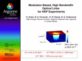
Evaluation of Multi-Gbps Optical Transceivers for Use in Future HEP Experiments Luis Amaral CERN – PH/ESE/BE – Opto 16/09/2008
Outline • Introduction • Optical Links Upgrade for SLHC • Project Organization • Commercial Optical Transceivers • Overview • Devices Under Test • Performance Evaluation of Commercial Optical Transceivers • Setups and Procedures • Performance metrics • Specification Proposal for Operation at 5Gbps • Analysis of the Data and Results • Figure of Merit • Results of the Devices Under Test • Summary Luis.Amaral@cern.ch
Optical Link Upgrade for LHC • The future SLHC upgrade is expected to increase the LHC luminosity by an order of magnitude. This implies: • More data to be transmitted; • Assuming more complex DAQ/TTC/SC systems. • Higher radiation doses. • The optical links are also required to have low power dissipation and to reduce the mass inside the detector. • The solution is to increase the bandwidth of each individual link. • The links will be required to: • Run at multi-Gbps speeds; • Have better radiation tolerance; • Operate at low temperatures and in strong magnetic field; • Be easy to install and operate. • The goal is to come up with a common solution that offers: • System architectures; • Basic building blocks. Luis.Amaral@cern.ch
Project Organization Luis.Amaral@cern.ch
Project Organization • The GBT project covers the ASIC design, verification and packaging. • The Versatile Link project covers system architectures and the components. • One of the main F.E. components is a Versatile Transceiver (VTRx), which results from the customization of a commercial transceiver (TRx). Luis.Amaral@cern.ch
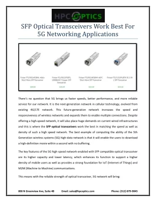
Commercial Transceivers Overview • The goal is the VTRx customization of a commercial TRx. • There are several families of commercial optical TRxs to target the Telecom and Datacom standards. • The GBT project specifies a single lane running at 4.8Gbps which is not a standard. SFP XFP SFP+ Luis.Amaral@cern.ch
Commercial Transceivers Overview • The goal is the VTRx customization of a commercial TRx. • There are several families of commercial optical TRxs to target the Telecom and Datacom standards. • The GBT project specifies a single lane running at 4.8Gbps which is not a standard. SFP XFP SFP+ SFP+ TRxs seem to be worthy of our attention. What are they made of? • CAGE • Controller (back) • LA • ROSA • LDD • TOSA SFPs are similar but rated for lower speeds and the XFPs include a clock and data recovery circuit on both Tx and Rx paths. Luis.Amaral@cern.ch
Devices Under Test • Our evaluation was guided towards the performance at 5Gbps, i.e. slightly faster than what the GBT protocol is targeting (4.8Gbps). • Some devices are suitable for MM links operating at 850nm and other are suitable for SM links operating at 1310nm. • Some devices have VCSELs (850 and 1310nm) and other have DFB lasers (1310nm). • Testboard • SFP+ module inside an assembly cage Luis.Amaral@cern.ch
Tx Performance Evaluation – Eye Diagram Luis.Amaral@cern.ch
Tx Performance Evaluation – Eye Diagram • Tx optical output and metrics: (1) The Tx jitter spec. is the 4GFC Tx jitter budget, not including the jitter of the test set-up. Luis.Amaral@cern.ch • by processing the Tx eye raw data
Tx Performance Evaluation – Mask Test • Tx Relative Mask • (based on the 4GFC spec.) • The mask defines an area which the eye diagram must not cross. • Although based on the 4GFC Tx mask, the jitter and slope are adjusted to the previous specifications and to the jitter of our test setup. • The maximum overshoot is 40% to allow laser driver pre-emphasis and because no filtering is being used. • The green arrows defines the mask margin from 0% to 100%. • The mask defines the limits for the overshoot and ringing but cannot be used to test jitter or rise/fall time compliance. • by processing the Tx eye raw data (2) The margins of the full and center mask must be measured as they will be used to compare different devices. Luis.Amaral@cern.ch
Rx Performance Evaluation – Eye and Mask Luis.Amaral@cern.ch
Rx Performance Evaluation – Eye and Mask • Rx Absolute Mask • (based on the SFP+ SFI spec. ) (3) The Rx jitter spec. is the 4GFC Rx jitter budget , not including the jitter of the test set-up. (4) Measured with an input OMA of 90uW. • Defines the limits for the electrical swing. Luis.Amaral@cern.ch
Rx Performance Evaluation – BER Luis.Amaral@cern.ch
Rx Performance Evaluation – BER • Rx BER curves – Two examples • By measuring the Bit Error Rate (BER) at different OMAs the BER curve is created. • The Rx sensitivity is defined as the minimum OMA which allows a 1E-12 BER. (5) Specified for a BER of 1E-12. (6) The sensitivity is specified as an OMA. The setup reads average power and the OMA is calculated using the Tx ER. Luis.Amaral@cern.ch
Evaluation of the TRx Power Dissipation • To measure the power dissipation we can simply read current being supplied to the host board. • The setup is to measure the power at different bitrates and Rx optical input levels. • In reality we measured the non end-of-life power dissipation at room temperature. (7) End-of-life power dissipation and across all operating temperatures and all Rx optical input levels. Our experience with commercial TRxs tells us that this spec. might be very harsh for non VCSEL-based transmitters. Luis.Amaral@cern.ch
Analysis of the Data • Flag devices non-compliant with the spec. Tx Performance at 5Gbps • The previous test setups generate a very large data set: raw eye diagrams, direct scope measurements, BER curves and measurements of the raw data. • As we are interested in the TRx performance at 5Gbps we discard all other bitrates and compare the measurements with the specification. Rx Performance at 5Gbps Power Dissipation • We flag the devices that do not meet the spec. and we have developed a Figure of Merit (FoM) that combines all the performance data into three numbers: for the Tx part (Tx_FoM), for the Rx part (Rx_FoM) and for the power dissipation (Pwr_FoM). Luis.Amaral@cern.ch
Figure of Merit There is a strong correlation between the performance of the device and the FoM number. • Worst • Tx • 139 • 171 • 183 • RED=FAIL • GREEN=PASS • Tx • Better • Tx • Best • Tx • SFP+ 10G 1310VCSEL #5 • SFP 4G 850VCSEL • SFP 4G 1310VCSEL • XFP 10G 1310DFB • SFP+ 10G 1310VCSEL #1 • SFP+ 10G 1310VCSEL #2 • SFP+ 10G 1310VCSEL #3 • SFP+ 10G 1310VCSEL #4 • SFP+ 10G 850VCSEL #1 • SFP+ 10G 850VCSEL #2 • SFP+ 10G 1310DFB #1 • SFP+ 10G 1310DFB #2 Luis.Amaral@cern.ch
Results • FAIL • PASS • FAIL • FAIL • PASS • SFP (devices 1 and 2): Tx problems with rise/fall times or jitter. Rx jitter problems. Both and Tx and Rx masks fail. • SFP+ 850mn VCSEL (devices 3 and 4): Good power dissipation and very good 5Gbps Tx performance. The sensitivity of the PINs at 850nm was found to be around -16dBm. The Rx jitter is good with 90uW of OMA (spec.). • SFP+ 1310mn DFB (devices 5 and 6): Good 5Gbps Tx performance but high power dissipation. The sensitivity of the PINs at 1310nm was found to be around -19dBm. • XFP 1310nm DFB (device 7): Great jitter performance but very high power dissipation. • SFP+ 1310mn VCSEL (devices 8 to 12): Great power dissipation and good 5Gbps Tx performance in most of the modules. Considerable overshoot and ringing. • The sensitivity of all 850nm PINs was found to about 3dB worse than the sensitivity of 1310nm PINs. • The only modules that were able to meet all 13 points of our spec. (Tx, Rx and power) were 850 and 1310nn VCSEL-based SFP+ modules. • Tx • Rx • Power Luis.Amaral@cern.ch
Summary • The future Versatile Transceiver will be • built from radiation-qualified optoelectronic components; • customized from a commercial transceiver. • Using commercial devices we have developed test methods for transceiver testing to • select a transceiver family for VTRx customization; • test the performance of the prototype VTRx modules. • The results from our evaluation of several commercial transceiver modules show that • the SFP+ is the most suitable candidate for VTRx customization; • to achieve low power dissipation we need to target VCSEL-based lasers; • there are 1310nm VCSEL diodes capable of being operated at 5Gbps with sufficient performance. Luis.Amaral@cern.ch
Extra Slides Luis.Amaral@cern.ch
Rx Performance Evaluation – Alternative • Jitter Histogram - Loopback vs. Reference Tx • Example Using of the Same Module • Sensitivity - Loopback vs. Reference Tx • Example Using 5 Units of the Same TRx • The Rx performance is not decoupled from the Tx. • The Jitter is from the entire TRx. • The sensitivity may be different and less consistent. Luis.Amaral@cern.ch
FoM Definition • Tx • Rx • Power Luis.Amaral@cern.ch
Results – Tx and Power SFP VCSEL modules: Problems with rise/fall times and jitter. The mask fails. SFP+ 850mn VCSEL modules: Good power dissipation and very good 5Gbps Tx performance. SFP+ 1310mn DFB modules: Good 5Gbps Tx performance but high power dissipation. XFP 1310nm DFB module: Great jitter performance but high power dissipation. SFP+ 1310mn VCSEL modules: Great power dissipation and good 5Gbps Tx performance in most of the modules. Considerable overshoot and ringing. • Tx_FoM • PWR_FoM • 1310nm VCSEL • 1310nm VCSEL • 850nm VCSEL • 850nm VCSEL • 1310nm DFB Luis.Amaral@cern.ch
Results – Rx and Overall Performance SFP modules: Our jitter spec. is too harsh for 4G SFP receivers. Also their electrical swing can be much higher than is allowed by our mask. Modules with 1310nm PINs: The sensitivity at 1E-12 was found to be around -19dBm (about 3dB better than with 850nm PINs). SFP+ with 850nm PINs: Using an input with an OMA of 90uW (spec.), the jitter seems not to be made worse by the lower sensitivity of 850nm PINs. Using this OMA the jitter seems to depend mostly on the electronics, i.e. TIA, LA and PCB design. • Rx_FoM • FoM (average of all 3) The only modules that were able to meet all 13 points of our spec. (Tx, Rx and power) were 850 and 1310nn VCSEL-based SFP+ modules. • Fall, Rx Jitter, Tx and Rx Mask • Tx and Rx Jitter and Mask • Power dissipation • OMA and Tx mask • Tx mask Luis.Amaral@cern.ch