Multiple Processor Systems
Multiple Processor Systems. Tanenbaum, Modern Operating Systems 3 e, (c) 2008 Prentice-Hall. Multiple Processor Systems. Figure 8-1. (a) A shared-memory multiprocessor. (b) A message-passing multicomputer. (c) A wide area distributed system.

Multiple Processor Systems
E N D
Presentation Transcript
Multiple Processor Systems Tanenbaum, Modern Operating Systems 3 e, (c) 2008 Prentice-Hall
Tanenbaum, Modern Operating Systems 3 e, (c) 2008 Prentice-Hall
Tanenbaum, Modern Operating Systems 3 e, (c) 2008 Prentice-Hall
Tanenbaum, Modern Operating Systems 3 e, (c) 2008 Prentice-Hall
Tanenbaum, Modern Operating Systems 3 e, (c) 2008 Prentice-Hall
Multiple Processor Systems Figure 8-1. (a) A shared-memory multiprocessor. (b) A message-passing multicomputer. (c) A wide area distributed system. (a) is a Uniform Memory Access (UMA) architecture, while (b) and (c) are Non-Uniform Memory Access (NUMA) architectures Tanenbaum, Modern Operating Systems 3 e, (c) 2008 Prentice-Hall
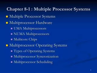
UMA Multiprocessors with Bus-Based Architectures Figure 8-2. Three bus-based multiprocessors. (a) Without caching. (b) With caching. (c) With caching and private memories. Tanenbaum, Modern Operating Systems 3 e, (c) 2008 Prentice-Hall
UMA Multiprocessors Using Crossbar Switches Figure 8-3. The “Dance Hall” approach: (a) An 8 × 8 crossbar switch. (b) An open crosspoint. (c) A closed crosspoint. Tanenbaum, Modern Operating Systems 3 e, (c) 2008 Prentice-Hall
Interconnection Technology (1) Figure 8-16. Various interconnect topologies. (a) A single switch. (b) A ring. (c) A grid. Tanenbaum, Modern Operating Systems 3 e, (c) 2008 Prentice-Hall
Interconnection Technology (2) Figure 8-16. Various interconnect topologies. (d) A double torus. (e) A cube. (f) A 4D hypercube. Tanenbaum, Modern Operating Systems 3 e, (c) 2008 Prentice-Hall
UMA Multiprocessors Using Multistage Switching Networks (1) Figure 8-4. (a) A 2 × 2 switch with two input lines, A and B, and two output lines, X and Y. (b) A message format. Tanenbaum, Modern Operating Systems 3 e, (c) 2008 Prentice-Hall
UMA Multiprocessors Using Multistage Switching Networks (2) Figure 8-5. An omega switching network. Tanenbaum, Modern Operating Systems 3 e, (c) 2008 Prentice-Hall
NUMA Multiprocessors (1) Characteristics of NUMA machines: • There is a single address space visible to all CPUs. • Access to remote memory is via LOAD and STORE instructions. • Access to remote memory is slower than access to local memory. Tanenbaum, Modern Operating Systems 3 e, (c) 2008 Prentice-Hall
NUMA Multiprocessors (2) Figure 8-6. (a) A 256-node directory-based multiprocessor. Tanenbaum, Modern Operating Systems 3 e, (c) 2008 Prentice-Hall
NUMA Multiprocessors (3) Figure 8-6. (b) Division of a 32-bit memory address into fields. (c) The directory at node 36. Tanenbaum, Modern Operating Systems 3 e, (c) 2008 Prentice-Hall
Each CPU Has Its Own Operating System Figure 8-7. Partitioning multiprocessor memory among four CPUs, but sharing a single copy of the operating system code. The boxes marked Data are the operating system’s private data for each CPU. Tanenbaum, Modern Operating Systems 3 e, (c) 2008 Prentice-Hall
Tanenbaum, Modern Operating Systems 3 e, (c) 2008 Prentice-Hall
Master-Slave Multiprocessors Figure 8-8. A master-slave multiprocessor model. Tanenbaum, Modern Operating Systems 3 e, (c) 2008 Prentice-Hall
Tanenbaum, Modern Operating Systems 3 e, (c) 2008 Prentice-Hall
Symmetric Multiprocessors Figure 8-9. The SMP multiprocessor model. Tanenbaum, Modern Operating Systems 3 e, (c) 2008 Prentice-Hall
Tanenbaum, Modern Operating Systems 3 e, (c) 2008 Prentice-Hall
Tanenbaum, Modern Operating Systems 3 e, (c) 2008 Prentice-Hall
Multiprocessor Synchronization (1) Figure 8-10. The TSL instruction can fail if the bus cannot be locked. These four steps show a sequence of events where the failure is demonstrated. Tanenbaum, Modern Operating Systems 3 e, (c) 2008 Prentice-Hall
TSL solution for multi-processors • TSL involves testing and setting memory, this can require 2 memory accesses • Not a problem to implement this in single-processor system • Now, bus must be locked to avoid split transaction • Bus provides a special line for locking • A process that fails to acquire lock checks repeatedly issuing more TSL instructions • Requires Exclusive access to memory block • Cache coherence protocol would generate lots of traffic • Goal: To reduce number of checks • Exponential back-off: instead of constant polling, check only after delaying (1, 2, 4, 8 instructions) • Maintain a list of processes waiting to acquire lock.
Busy-Waiting vs Process switch • In single-processors, if a process is waiting to acquire lock, OS schedules another ready process • OS must decide whether to switch (choice between spinning and switching) • spinning wastes CPU cycles • switching uses up CPU cycles also • possible to make separate decision each time locked mutex encountered
Multiprocessor Synchronization (2) Figure 8-11. Use of multiple locks to avoid cache thrashing. Tanenbaum, Modern Operating Systems 3 e, (c) 2008 Prentice-Hall
Timesharing Figure 8-12. Using a single data structure for scheduling a multiprocessor. Tanenbaum, Modern Operating Systems 3 e, (c) 2008 Prentice-Hall
Space Sharing Figure 8-13. A set of 32 CPUs split into four partitions, with two CPUs available. Tanenbaum, Modern Operating Systems 3 e, (c) 2008 Prentice-Hall
Gang Scheduling (1) Figure 8-14. Communication between two threads belonging to thread A that are running out of phase. Tanenbaum, Modern Operating Systems 3 e, (c) 2008 Prentice-Hall
Gang Scheduling (2) The three parts of gang scheduling: • Groups of related threads are scheduled as a unit, a gang. • All members of a gang run simultaneously, on different timeshared CPUs. • All gang members start and end their time slices together. Tanenbaum, Modern Operating Systems 3 e, (c) 2008 Prentice-Hall
Gang Scheduling (3) Figure 8-15. Gang scheduling. Tanenbaum, Modern Operating Systems 3 e, (c) 2008 Prentice-Hall
Interconnection Technology (3) Figure 8-17. Store-and-forward packet switching. Tanenbaum, Modern Operating Systems 3 e, (c) 2008 Prentice-Hall
Network Interfaces Figure 8-18. Position of the network interface boards in a multicomputer. Tanenbaum, Modern Operating Systems 3 e, (c) 2008 Prentice-Hall
Blocking versus Nonblocking Calls (1) Figure 8-19. (a) A blocking send call. Tanenbaum, Modern Operating Systems 3 e, (c) 2008 Prentice-Hall
Blocking versus Nonblocking Calls (2) Figure 8-19. (b) A nonblocking send call. Tanenbaum, Modern Operating Systems 3 e, (c) 2008 Prentice-Hall
Blocking versus Nonblocking Calls (3) Choices on the sending side: • Blocking send (CPU idle during message transmission). • Nonblocking send with copy (CPU time wasted for the extra copy). • Nonblocking send with interrupt (makes programming difficult). • Copy on write (extra copy probably needed eventually). Tanenbaum, Modern Operating Systems 3 e, (c) 2008 Prentice-Hall
Remote Procedure Call Figure 8-20. Steps in making a remote procedure call. The stubs are shaded gray. Tanenbaum, Modern Operating Systems 3 e, (c) 2008 Prentice-Hall
RPC Mechanism Client computer Server computer service procedure Execute procedure client Send reply Send request Marshal arguments Local call Marshal results Receive reply Unmarshal results Receive request Unmarshal arguments Local return server stub proc. client stub proc. Select procedure Communication module
Distributed Shared Memory (1) Figure 8-21. Various layers where shared memory can be implemented. (a) The hardware. Tanenbaum, Modern Operating Systems 3 e, (c) 2008 Prentice-Hall
Distributed Shared Memory (2) Figure 8-21. Various layers where shared memory can be implemented. (b) The operating system. Tanenbaum, Modern Operating Systems 3 e, (c) 2008 Prentice-Hall
Distributed Shared Memory (3) Figure 8-21. Various layers where shared memory can be implemented. (c) User-level software. Tanenbaum, Modern Operating Systems 3 e, (c) 2008 Prentice-Hall
Distributed Shared Memory (4) Figure 8-22. (a) Pages of the address space distributed among four machines. Tanenbaum, Modern Operating Systems 3 e, (c) 2008 Prentice-Hall
Distributed Shared Memory (5) Figure 8-22. (b) Situation after CPU 1 references page 10 and the page is moved there. Tanenbaum, Modern Operating Systems 3 e, (c) 2008 Prentice-Hall
Distributed Shared Memory (6) Figure 8-22. (c) Situation if page 10 is read only and replication is used. Tanenbaum, Modern Operating Systems 3 e, (c) 2008 Prentice-Hall
False Sharing Figure 8-23. False sharing of a page containing two unrelated variables. Tanenbaum, Modern Operating Systems 3 e, (c) 2008 Prentice-Hall
A Graph-Theoretic Deterministic Algorithm Figure 8-24. Two ways of allocating nine processes to three nodes. Tanenbaum, Modern Operating Systems 3 e, (c) 2008 Prentice-Hall
A Sender-Initiated Distributed Heuristic Algorithm Figure 8-25. (a) An overloaded node looking for a lightly loaded node to hand off processes to. (b) An empty node looking for work to do. Tanenbaum, Modern Operating Systems 3 e, (c) 2008 Prentice-Hall