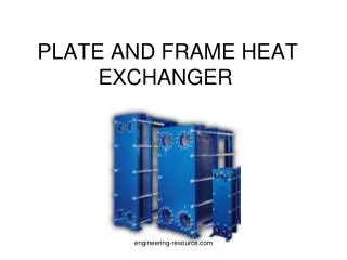
PLATE AND FRAME HEAT EXCHANGER
1.37k likes | 4.79k Vues
PLATE AND FRAME HEAT EXCHANGER . PRESENTED BY. HAFEERA SHABBIR 06-CHEM-19 MUBASHRA LATIF 06-CHEM-23 PAKEEZA TARIQ MEER 06-CHEM-65 MAHPARA MUGHAL 06-CHEM-69. OUTLINE. Introduction Construction Principle of Operation Applications Advantages

PLATE AND FRAME HEAT EXCHANGER
E N D
Presentation Transcript
PLATE AND FRAME HEAT EXCHANGER engineering-resource.com
PRESENTED BY • HAFEERA SHABBIR 06-CHEM-19 • MUBASHRA LATIF 06-CHEM-23 • PAKEEZA TARIQ MEER 06-CHEM-65 • MAHPARA MUGHAL 06-CHEM-69 engineering-resource.com
OUTLINE • Introduction • Construction • Principle of Operation • Applications • Advantages • Limitations of Operation • Comparison of with STH • Design steps with Solved example engineering-resource.com
Introduction • It is a type of compact heat exchanger • A plate heat exchanger is a type of heat exchanger that uses metal plates to transfer heat between two fluids engineering-resource.com
CONSTRUCTION • Based on their construction plate and frame heat exchangers are classified into • (a) Gasketed–plate • (b) Welded-plate engineering-resource.com
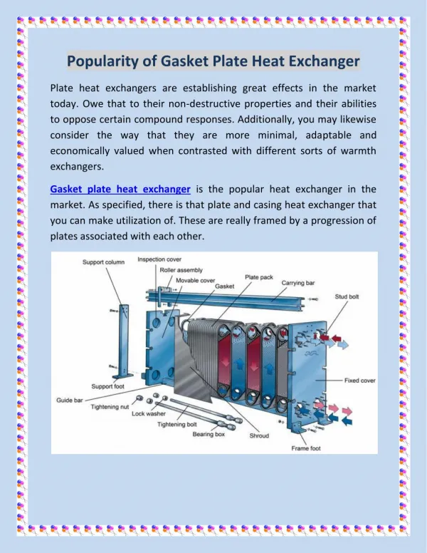
GASKETED-PLATE HEAT EXCHANGER(GPHE) • Parallel corrugated plates clamped in a frame with each plate sealed by gaskets and with four corners ports, one pair for each of the two fluids. • The fluids are at all times separated by 2 gaskets, each open to the atmosphere. Gasket failure cannot result in fluid intermixing but merely in leakage to atmosphere, hence a protective cover is there. engineering-resource.com
Construction of GPHE • Plates • Gaskets • Plate frame engineering-resource.com
PLATES • Plate thickness is 0.4 to 0.8 mm • Channel lengths are 2-3 meters • Plates are available in: Stainless Steel, Titanium, Titanium-Palladium, Nickel engineering-resource.com
PLATES PATTERNS 1)Induce turbulence for high HT coefficient 2)Reinforcement and plate support points that maintains inter-plate separation. TYPES OF PATTERNS • Mainly 2 types of patterns (corrugations) are used 1)Intermating or washboard corrugations 2)Chevron or herringbone corrugations engineering-resource.com
CHEVRON OR HERRINGBONE • Most common type • Corrugations are pressed to same depth as plate spacing • Operate at High pressure • Corrugation depth 3mm to 5mm • Velocity 0.1 to 1 m/s engineering-resource.com
CHEVRON CORRUGATIONS engineering-resource.com
INTERMATING TROUGH PATTERNS • Pressed deeper than spacing • Fewer connection points • Operate at Lower pressure • Max channel gap 3mm to 5mm • Min channel gap 1.5 mm to 3 mm • Velocity range in turbulent region is 0.2 to 3 m/s engineering-resource.com
DIMPLE CORRUGATIONS engineering-resource.com
GASKETS • They limit the maximum operating temperature for a plate heat exchanger. Material selection depends upon 1)Chemical resistance 2)Temperature resistance 3)Sealing properties 4)Shape over an acceptable period of time engineering-resource.com
GASKET MATERIALS • Typical gasket materials are Natural rubber styrene Resin cured butyl Compressed asbestos fiber gaskets engineering-resource.com
FRAMES • Materials 1)Carbon steel with a synthetic resin finish 2)stainless steel engineering-resource.com
WELDED PLATE HEAT EXCHAGERS(WPHE) • Developed to overcome the limitations of the gasket in GPHE • Inabilty of heat transfer area inspection and mechanical cleaning of that surface engineering-resource.com
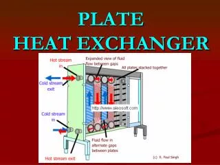
OPERATION • Channels are formed between the plates and corner ports are arranged so that the two media flow through alternate channels. • The heat is transferred through the thin plate between the channels, and complete counter current flow is created for highest possible efficiency. No intermixing of the media or leakage to the surroundings will take place as gaskets around the edges of the plates seal the unit. engineering-resource.com
APPLICATIONS 3 major applications • (1)liquid-liquid services • (2)condensing and evaporative • (3)Central cooling engineering-resource.com
LIQUID-LIQUID SERVICES • It is well-suited to liquid/liquid duties in turbulent flow, i.e. a fluid sufficiently viscous to produce laminar flow in a smooth surface heat exchanger may well be in turbulent flow in PHE. • It has major applications in the food industry. engineering-resource.com
CONDENSATION AND VAPORIZATION • Condensation of vapor (including steam) at moderate pressure, say 6 to 60 Psi, is also economically handled by PHE’s, but duties involving large volumes of very low pressure gas or vapor are better suited to other forms of heat exchangers engineering-resource.com
CENTRAL COOLING • It is the cooling of a closed circuit of fresh non-corrosive and non-fouling water for use inside a plant, by means of brackish water. Central coolers are made of titanium, to withstand the brackish water engineering-resource.com
ADVANTAGES • Compactness • Flexibility • Very high heat transfer coefficients on both sides of the exchanger • Close approach temperatures and fully counter-current flow • Ease of maintenance. Heat transfer area can be added or subtracted with out complete dismantling the equipment engineering-resource.com
CONTD….. • Ease of inspection on both sides • Ease of cleaning • Savings in required flow area • Low hold-up volume • Low cost • No Local over heating and possibility of stagnant zones is also reduced • Fouling tendency is less engineering-resource.com
LIMITATIONS • Low Pressure upto 300 psi • Low temperature upto 300 F • Limited capacity • Limited plate size 0.02 sq.m to 1.5 sq.m engineering-resource.com
Large difference b/w flow rates cant be handled • High pressure drop • Potential for leakage engineering-resource.com
COMPARISON BETWEEN PHE AND STHE engineering-resource.com
DESIGN STEPS WITH SOLVED EXAMPLE engineering-resource.com
STATEMENT OF PROBLEM • A plate heat exchanger was use to preheat 4 kg/s of dowtherm from 10 to 70◦C with a hot water condensate that was cooled from 95 to 60◦C.Determine the number of plates required for a single-pass counter flow plate and frame exchanger. Assume that each mild stainless-steel plate [kw=45j/s.m.K]has a length of 1.0m and a width of 0.25m with a spacing between the plates of 0.005m.Also,estimate the pressure drop of the hot water stream as it flows through the exchanger. engineering-resource.com
DATA REQUIRED • The performance characteristics for the chevron configuration selected for the plates are shown . For • Re > 100,Nu and f can be represented by the following relationships: • Nu = 0.4 Re0.64Pr0.4 • f = 2.78Re-0.18 • : engineering-resource.com
ASSUMPTIONS • The plate heat exchanger operates under steady state conditions. • No phase change occurs: both fluids are single phase and are unmixed. • Heat losses are negligible; the exchanger shell is adiabatic. • The temperature in the fluid streams is uniform over the flow cross section. • There is no thermal energy source or sink in the heat exchanger. • The fluids have constant specific heats. • The fouling resistance is negligible. engineering-resource.com
Properties of each fluid at the mean temperature in the exchanger are property Dowtherm at 40 ◦C Water at 77◦C 4.198*103J/kg.K Heat capacity CP 1.622*103 J/kg.K 0.138 J/.m.K Thermal conductivity k 0.668J/s.m.K Viscosity µ 3.72*10-4Pa.s 2.70*10-3Pa.s Density ρ 1.044*102kg/m3 9.74*102kg/m3 engineering-resource.com
SOLUTION • APPROACH TO THE PROBLEM: • To avoid an iterative calculation because of the interdependency between the heat transfer area and the total flow area, use the NTU approach to determine the NTUmin required, noting that NTUmin=UA/(mCp)min.the area of the plate and frame exchanger can be calculated once the overall heat transfer coefficient has been evaluated. engineering-resource.com
CALCULATION OF HT AREA • For a single pass configuration with Np plates and NP+1 flow passages ,solution of the problem can be simplified mathematically by assuming n flow passages and n-1 plates ,since flow velocities involve flow passages and not plates. with this modification, the heat transfer surface area of the exchanger in terms of n is • A=(n-1)LW=(n-1)(1)(0.25)=0.25(n-1)m2 engineering-resource.com
CALCULATION OF FLOW AREA • The flow area for each stream with n/2flow passages is given by: S=n/2(W)(b) =n/2(0.25)(0.005) =(6.25*10-4)n. engineering-resource.com
CALCULATION OF HEAT DUTYAND FLOW RATES TOTAL RATE OF HEAT TRANSFER: FOR DOWTHERM q= (mCpΛT)c =4(1.622*103)(70-10) =3.89*105W THE MASS FLOW RATE OF WATER : mh=q/(CPΛT)h =3.89*105/(4.198*103)(95-60) =2.65 Kg/s VELOCITY OF WATER: Vh =mh /ρhS =2.65/(9.74*102)(6.25*10-4)n =(4.35/n)m/s engineering-resource.com
EQUIVALENT DIAMETER: De=2b =0.01m engineering-resource.com
CALCULATION OF HOT SIDE HT COEFFICIENT • REYNOLD NUMBER: Reh=DeVhρh /µh =0.01(4.35/n)(9.74*102)/(3.72*10-4) =1.139*105/n This indicates that Reynold number is greater than 100 and correlation for Nu can be used. Pr NUMBER: Prh = Cpµ/k = (4.198*103)(3.72*10-4)/0.668 =2.34 • hh =(0.4)(kh/De)Re0.64Pr0.4 =[0.668/0.01][1.139*105/n]0.64(2.34)0.4 =6.467*104/n0.64W/m2.K engineering-resource.com
CALCULATION OF COLD SIDE HT COEFFICIENT The same calculations are repeated for cold stream. V=mc/ρc S =4.0/(1.044*103)(6.25*10-4)n =6.13/n Re=DeVcρc/µc =0.01(6.13/n)(1.044*103)/(2.70*10-3) =2.37*104/n Prc=(1.622*103)(2.70*10-3)/(0.138) =31.73 This also indicates that Re>100 hc=(0.4)(kc/De)Re0.64Pr0.4 =(0.4)(0.138/0.01)(237*104/n)0.64 (31.73)0.4 =1.388*104 /n0.64 W/m2.K engineering-resource.com
CALCULATION OF OVERALL HT COEFFICIENT • The overall heat transfer coefficient can now be determined in terms of n. Since the surface areas on either side of the plate are the same, no correction for area is required. • Assume a thickness of the plate xw of 0.0032m 1/U=1/hh+xw/kw+1/hc =n0.64/(6.467*104)+(0.0032)/(45)+n0.64/(1.388*104) =8.751*10-5n0.647+7.11*10-5 m. K/W engineering-resource.com
USING THE NTU METHOD • A NTUmin for cold stream with a minimum mcp is defined NTUmin=UA/(Mcp)min =Tc,out–Tc,in/ fΛT◦,log mean LOG MEAN TEMPERATURE DIFF: ΛT◦,log mean: =(Th,in-Tc,out)-(Th,out–Tc,in)/ln[(Th,in-Tc,out)/Th,out-Tc,in)] =(95-70)-(60-10)/ln[(95-70)/(60-10)] =36.067 K. • For a single pass counter flow plate and frame heat exchanger ,F=1. engineering-resource.com
NTU =70-10/36.067 =1.664 • To satisfy the other NTU definition of UA/(Mc) in terms of results in the relation 1 0.25(n-1) 1.664 = ( )( ) 8.751*105n0.64+7.11*10-5 4.0(1.622*103) engineering-resource.com
ITERATIVE METHOD • This equation can be solved with itreration to indicate that n=51.Thus 50 plates are required to meet to the heat transfer needs to preheat 4kg/s of dowtherm from 10 to 70◦C. engineering-resource.com