Lecture 4: Medium Access Control
This lecture covers the essential aspects of Medium Access Control (MAC) in networking, focusing on how shared mediums are managed. It explores the structure of communication protocols, including architecture and layering. Key MAC protocols like TDMA, FDMA, and CDMA are examined in detail. The lecture also discusses the goals of MAC protocols such as efficiency, fairness, and low latency. Moreover, it highlights different link technologies and their implications for error control and reliability. The physical limitations of medium access, represented through real-world examples, are also presented.

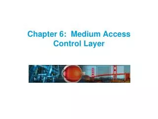
Lecture 4: Medium Access Control
E N D
Presentation Transcript
Lecture 4: Medium Access Control CS 3035/GZ01: Networked Systems Kyle Jamieson Department of Computer Science University College London
Structure of 3035/GZ01 • Start with architecture • Protocols: How to structure communication • Layering: How to leverage modularity • Then move to the lower layers • Link technologies • Coping with errors • Study the “narrow waist” of IP • IP best-effort forwarding • IP addressing • Routing: Intra-, Inter-Domain (BGP) • Building on top of the narrow waist • TCP reliable transport, congestion control • Domain name system (DNS) • Security, web caching, CDNs
Review: The data link layer • Enables exchange of atomic messages (frames) between end hosts • Determine start and end of bits and frames (framing) • Deliver information reliably • Control errors (last lecture) • Some link layers involve a shared medium • e.g., Shared-wire Ethernet, satellite uplink, WiFi • Today: Medium access control to share the medium
Medium access: the problem • Two questions: • How should the shared medium be divided? • Who gets to talk on a shared medium, and when? • A medium access control (MAC) protocol specifies the above • Three goals of a MAC protocol: • Efficiency • High throughput(bits/second successfully received through the channel) • High utilization(throughput/raw channel rate) • Fairness: all hosts with data to send should get a roughly equal share of the medium over time • Latency: want to minimize the time a host waits before being granted permission to talk on the shared medium
Physical limitation: finite speed of light Boston via Geosync Satellite 0.2 s Hawaii From London to: 58 ms San Francisco 43 ms Paris WiMAX Base station 1.7 ms Mobile Base station 10 μs 1 μs WiFi AP 10−100 ns 343 km 3−30 m 300 m 3 km 8,645 km 12,000 km 73,000 km
Similar MAC protocols, vastly different timescales Geosynchronous Satellite 0.2 s Packet radio: ALOHA WiMAX Base station 10 μs Ethernet CSMA/CD WiFi: CSMA/CA 10−100 ns 3−30 m 3 km 73,000 km
Today • Channel partitioning: • Time division multiple access (TDMA) • Frequency division multiple access (FDMA) • Code division multiple access (CDMA) • Random access protocol: ALOHA • Unslotted ALOHA • Slotted ALOHA • Random access protocol: the Ethernet
TDMA: Time Division Multiple Access • Access to channel in “rounds” • Each station gets fixed length slot (packet time) in each round (unused slots go idle) • Example:six stations, only 1, 3, and 4 have data to send 6-slot round 1 4 1 4 3 3 Time
FDMA: Frequency Division Multiple Access • Channel spectrum divided into frequency bands • Each station assigned fixed frequency band(unused frequency bands are wasted) • Example:six stations, only 1, 3, and 4 have data to send time frequency bands FDM cable
CDMA: Code Division Multiple Access • CDMA is a medium access protocol used in wireless networks • All users transmit over the same frequencies, and at the same time • Another example of the use of codes • But for sharing, instead of error control • Codes allow multiple users to coexist and transmit simultaneously with no interference, in theory • In practice: performs well (many cellular mobile telephone networks use CDMA)
1 1 1 1 1 1 1 1 1 1 1 1 1 1 1 1 - - - - - - - - - - - - - - - - 1 1 1 1 1 1 1 1 1 1 1 1 1 1 1 1 CDMA: User codes • Each user nhas her own binary “chip” code cnof length M • Represent binary data and binary code using { 1, −1 } • Encoding at user i: • For each data bit dk, form M repetitions of dk, then multiply the result, bit-by-bit, with cn d1= 1 User 1 data: Channel output for user 1: d0= -1 × = • e.g. (user 1, M = 8): User 1 code: c1 c1
1 1 1 1 1 1 1 1 1 1 1 1 1 1 1 1 - - - - - - - - - - - - - - - - 1 1 1 1 1 1 1 1 1 1 1 1 1 1 1 1 CDMA: Code rate • Chip rate = raw channel rate B • Data rate = B/M(M times slowerthan raw channel rate) • Overall code rate R = 1/M • e.g. (user 1, M = 8): d1= 1 User 1 data: User 1’s transmission: d0= -1 Rate: B/M × = User 1 code: Rate: B c1 c1
1 1 1 1 - - - - - - - - - - - - - - - - 1 1 1 1 1 1 1 1 1 1 1 1 1 1 1 1 Decoding a single CDMA transmission • Receiver hears Zi,m: mth chip for ith data bit • To decode data bit i, receiver multiplies what it hears with user 1’s code, chip by chip: Received data Zi,m: 1 1 1 1 × = d0 = 1 d1 = -1 User 1 code: 1 1 1 1 1 1 1 1
Sharing the medium with CDMA • Let’s assume we have a way of: • Synchronizing all users’ data bits in time • Synchronizing all users’ chips in time • In many shared mediums (e.g. wireless, but not optical), principle of linearity applies: • The channel sums the transmitted signals together, as shown: × User 1: × User 2: Result: Wireless interference
CDMA:Separating users’ transmissions • As before, receiver selects user 1’s code c1, and multiplies the received signal Zi,m by c1, chip by chip: • User 2’s interference is completely cancelled × Receiver (listening to User 1):
CDMA: How to choose codes • Two users: user 1 (code c1), user 2 (code c2) • When the receiver “tuned” to data bit 1 from user 1: User 1: User 2:
CDMA: How to choose codes Orthogonality condition: User 1: User 2:
Example of CDMA codes: Walsh codes • nth user’s length-NWalsh code is the nth row of an N × NHadamard matrix H(N) • Code rate: 1/N • Supports up to N concurrent users
Do Walsh codes have the orthogonality property? • Let’s look at the two rows of H(2)… yes! • Assuming rows of H(2k−1) is orthogonal, let’s imagine a walk across two rows of H(2k), multiplying them term-by-term • We pick two rows, both in upper or both in lower half Product of the two is 0 + 0 • We pick one row in upper half, one in lower half, but samerespective rows of H(2k−1) Product of the two is 2k−1 − 2k−1 • We pick one row in upper half, one in lower half, but different respective rows of H(2k−1) Product of the two is 0 + 0
Today • Channel partitioning: • Time division multiple access (TDMA) • Frequency division multiple access (FDMA) • Code division multiple access (CDMA) • Random access protocol: ALOHA • Unslotted ALOHA • Slotted ALOHA • Random access protocol: the Ethernet
Random access MAC protocols • When a station has a frame to send: • Transmit at full channel data rateB • No a priori coordination among nodes • Two or moreframes overlapping in time: collision • Both frames are lost, resulting in diminished throughput • A random access MAC protocol specifies: • How to detect collisions • How to recover from collisions
ALOHAnet: Context • Norm Abramson, 1970 at the University of Hawaii • Seven campuses on four islands • Want to keep campus terminals in contact with mainframe • Telephone costs high, so build a packet radio network
Unslotted ALOHA • Simplest possible medium access control: no control at all, anyone can just transmit a packet without delay • Let’s assume that the probability a packet begins in any time interval of length Δt is λ × Δt • N senders in total, sending frames of time duration 1 • This is called a Poisson process with rate λ • λ is the aggregate rate from all N senders • Individual rate λ/N for each sender
Unslotted ALOHA: Performance • Suppose some node i is transmitting; let’s focus on i’s frame Vulnerable period • If others send between t0−1 and t0, their frames will overlap with the start of i’s frame collision • If others send between t0 and t0+1, their frames will overlap with end of i’s frame collision • Otherwise, no collision, and node i’s frame is delivered • Therefore, there is a “vulnerable period” of length 2 around i’s frame
Unslotted ALOHA: Performance Vulnerable period • What’s the chance no one else sends in the vulnerable period of length 2?
Unslotted ALOHA: Utilization Utilization 1/2e ≈ 18% Too many collisions! Not sending fast enough λ • Recall from our definition of the Poisson process:λ is the aggregate rate from all senders • So, utilization = λ × Pr(no other transmission in 2) = λe−2λ
Today • Channel partitioning: • Time division multiple access (TDMA) • Frequency division multiple access (FDMA) • Code division multiple access (CDMA) • Random access protocol: ALOHA • Unslotted ALOHA • Slotted ALOHA • Random access protocol: the Ethernet
Slotted ALOHA • Divide time into slots of duration 1, synchronizeso that nodes transmit onlyin a slot • Each of N nodes transmits with probability p in each slot • So aggregate transmission rate λ = N × p • As before, if there is exactly one transmission in a slot, can receive; if two or more in a slot, no one can receive (collision) ... Node N
Slotted ALOHA: Utilization Suppose N nodes, each transmit with probability p in each slot. What is the utilization as a function of aggregate rate λ = N × p? • Pr[A node is successful in a slot] = p(1−p)N−1 • Pr[Success in a slot] = Np(1−p)N−1 Utilization 1/e ≈ 37% λ
ALOHA throughput: slotted versus unslotted 1/e ≈ 36% Slotted ALOHA:λe−λ 1/2e ≈ 18% Just by forcing nodes to transmit on slot boundaries, we double peak medium utilization! Unslotted ALOHA: λe−2λ
Today • Tour of medium access protocols (TDMA, FDMA, CDMA) • Random access protocol: ALOHA • Unslotted ALOHA • Slotted ALOHA • Random access protocol: the Ethernet
How did the Ethernet get built? • Bob Metcalfe, PhD student at Harvard in early 1970s • Working on protocols for the ARPAnet • Intern at Xerox Palo Alto Research Center (PARC), 1973 • Needed a way to network the ≈100 Alto workstations in-building • Adapt ALOHA packet radio • Metcalfe later founds 3Com, acquired by HP in April ’10 for USD $2.7 bn
The Ethernet: Physical design • Coaxial cable, propagation delay τ • Propagation speed: 3/5 × speed of light • Experimental Ethernet • Data rate: B = 3 Mbits/s • Maximum length: 1000 m Propagation delay: τ
Building the link: Framing bits • Goal: Move bits from one place to another • Sender and receiver have independent clocks • No separate “clock signal” sent on the Ethernet • Problem: Agree on clock tick period • Problem: Agree on clock tick alignment (phase)
How to encode bits? • Simple binary encoding is called Nonreturn to Zero (NRZ) • Drawback: Baseline wander prevents receiver from using average of received signal to distinguish between 1 and 0 • Drawback: Clock recovery in the presence of long runs of 0s or 1s in the data • Nonreturn to Zero Inverted (NRZI): Transition for a “1”, no transition for a “0”
Manchester (phase) encoding • Manchester encoding: • Exclusive-OR of the NRZ signal and the clock signal • “0” is a low-to-high transition; “1” is a high-to-low • Transition guaranteed on every bit • “Phase encoding” in the experimental Ethernet [Metcalfe et al.] • Drawback: Halves data rate
4B/5B encoding • So instead, later Ethernet standards use a block code called 4B/5B • Properties • No code has more than one leading zero • No code has more than two trailing zeros • When sent back-to-back, no pair of 5-bit codes contains more than three consecutive zeros • Encoding process: • Encode data using lookup table • Send coded bits with NRZI 4-bit data 0000 0001 0010 0011 0100 0101 0110 0111 1000 1001 1010 1011 1100 1101 1110 1111 5-bit code 11110 01001 10100 10101 01010 01011 01110 01111 10010 10011 10110 10111 11010 11011 11100 11101
Ethernet framing • Framing • Beginning of frame determined by presence of carrier • End of frame determined by absence of carrier • Preamble: 10101010 produces a square wave that allows receiver to frame bits • CRC (Cyclic Redundancy Check) protects against errors on the Ether • Does not guard against errors introduced by the tap: rely on higher-layer checksums • Destination address allows filtering at the link layer Preamble Destination Source Data CRC 8 bits 8 bits 4000 bits 16 bits
Collisions • Packet of N bits: N/B seconds on the wire • From the perspective of a receiver (B): • Overlapping packets at B means signals sum • Not time-synchronized: result is bit errors at B • No fate-sharing among receivers: C receives okay in this example Propagation delay: τ seconds B C Z A
Who gets to transmit? Carrier Sense Multiple Access with Collision Detection (CSMA/CD) • Begin the transmission procedure at any time • Carrier sensing: never transmit a frame if you sense that another station is transmitting • Collision detection: while sending, immediately abort your transmission if you detect another station transmitting
Carrier sensing • Mechanism: measure voltage on the wire • Binary encoding: voltage depends on the data • Manchester coding: constant average voltage
Collision detection • Paper isn’t clear on this point (authors did have a patent in the filing process) • Mechanism: monitor average voltage on cable • Manchester encoding means your transmission will have a predictable average voltage V0; others will increase V0 • Abort transmission immediately if Vmeasured > V0 C Z A B Propagation delay: τ seconds
When does a collision happen? • Suppose Station A begins transmitting at time 0 • Assume that the packet lasts much longer than τ • All stations sense transmission and defer by time τ • Don’t begin any new transmissions • At time τ, will a packet be collision-free? Only if no other transmissions began before time τ C Z A B Propagation delay: τ seconds
How long does a collision take to detect? • Suppose Station A begins transmitting at time 0 • τ seconds after Z starts, A hears Z’s transmission • When does A know whether its packet collided or not? At time 2τ C Z A B Propagation delay: τ seconds
Collision detection and packet size • How big must packets be for collisions to be detectable? • Transmit rate B bits/second • If packets take time 2τ, A will still be transmitting when Z’s packet arrives at A, so A will detect collision • So minimum packet size > 2τB bits • Experimental Ethernet: • τ = 5 μs, B = 3 Mbits/s → 2τB = 30 bits • Why doesn’t Metcalfe & Boggs paper mention this? C B Z A Propagation delay: τ seconds
Commercial Ethernet • Commercial Ethernet • Data rate B = 10 Mbits/s • Maximum length: 500 m per segment with up to two repeaters (hubs) • Repeater receives bits, relays them onto wire • τ = 20 μs worst case → 2τB = 400 bits = 50 bytes • Could send complete packet; not see collision repeater C Z A B Propagation delay: τ seconds
Resolving collisions • Upon abort (carrier detect), a station enters the backoff state • Key idea: the colliding stations all wait a random time before carrier sensing and transmitting again • How to pick the random waiting time? (Should be based on how stations have data to send) • How to estimate the number of colliding stations? • Goal: Engineer such that nodes will wait different amounts of time, carrier sense, and not collide
Slotted Ethernet backoff • Backoff time is slotted and random • Station’s view of the where the first slot begins is at the end of the busy medium • Random choice of slots within a window, the contention window (CW) • Goal: Choose slot time so that different nodes picking different slots carrier sense and defer, thus don’t collide
Picking the length of a backoff slot • Consider from the perspective of one packet • Transmissions beginning > τ before will cause packet to defer • Transmissions beginning > τ after willnot happen (why not?) • Transmissions beginning < time τ apart will collide with packet • So should we pick a backoff slot length of τ? OK Bad OK τ τ Cause defer CS fail (Won’t happen)
The problem of clock skew • No! Slots are timed off the tail-end of the last packet • Therefore, stations’ clocks differby at most τ • This is called clockskew Δ (−τ < Δ < τ) • Suppose we use a backoff slot length of τ • Different stations picking different slots maycollide! 1 2 0 τ τ OK OK Δ Station A, slot 1 τ τ Station B, slot 0 0 1 2