Download
1 / 25
250 likes | 282 Vues
Delve into the mechanisms of ductile and brittle fractures, impact testing, and fracture resistance in materials engineering, addressing factors influencing failure. Learn to identify and mitigate stress concentration for enhanced design performance.

E N D
Materials Engineering – Day 3 Quick Review of Hardness & Hardness Testing Big problem: when ductile materials go brittle… Impact Testing Ductile to Brittle Transition Temperature Introduction to Fracture. See how far we get.
Chapter 8: Mechanical Failure ISSUES TO ADDRESS... • How do flaws in a material initiate failure? • How is fracture resistance quantified; how do different material classes compare? • How do we estimate the stress to fracture? • How do loading rate, loading history, and temperature affect the failure stress? Computer chip-cyclic thermal loading. Hip implant-cyclic loading from walking. Ship-cyclic loading from waves. Adapted from Fig. 22.30(b), Callister 7e. (Fig. 22.30(b) is courtesy of National Semiconductor Corporation.) Adapted from Fig. 22.26(b), Callister 7e. Adapted from chapter-opening photograph, Chapter 8, Callister 7e. (by Neil Boenzi, The New York Times.)
Ductile vs. Brittle Behavior • Let us look at some pictures of failure in metal. Here they are. • Notes on Brittle • Gross deformation is not great • Failure is by cleavage mechanism • Fracture surface is faceted and shiny • Notes on Ductile • Gross deformation is visible • Failure is by microvoid coalescence • Fracture surface is dimpled and dull
Very Moderately Fracture Brittle Ductile Ductile behavior: %AR or %EL Large Moderate Small Ductile vs Brittle Failure • Classification: Adapted from Fig. 8.1, Callister 7e. • Ductile fracture is usually desirable! Ductile: warning before fracture Brittle: No warning
Example: Failure of a Pipe • Brittle failure: --many pieces --small deformation • Ductile failure: --one piece --large deformation Figures from V.J. Colangelo and F.A. Heiser, Analysis of Metallurgical Failures (2nd ed.), Fig. 4.1(a) and (b), p. 66 John Wiley and Sons, Inc., 1987. Used with permission.
Ductile vs. Brittle Failure cup-and-cone fracture brittle fracture Adapted from Fig. 8.3, Callister 7e.
Brittle Failure Arrows indicate pt at which failure originated Adapted from Fig. 8.5(a), Callister 7e.
http://pwatlas.mt.umist.ac.uk/internetmicroscope/micrographs/failure/brittle-steel.htmlhttp://pwatlas.mt.umist.ac.uk/internetmicroscope/micrographs/failure/brittle-steel.html
Stress Concentration What is it? Changes in geometry (holes, fillets, threads, notches) can cause local increases in stress (stress raisers) For example: Near a small hole in a large plate, the stress at the edge of the hole is three times as high as the stress away from the hole.
Concentration of Stress at Crack Tip Adapted from Fig. 8.8(b), Callister 7e.
s o max Stress Conc. Factor, K t = s o w s 2.5 max h r , 2.0 increasing w/h fillet radius 1.5 r/h 1.0 0 0.5 1.0 sharper fillet radius Engineering Fracture Design • Avoid sharp corners! s Adapted from Fig. 8.2W(c), Callister 6e. (Fig. 8.2W(c) is from G.H. Neugebauer, Prod. Eng. (NY), Vol. 14, pp. 82-87 1943.)
More on Stress Concentration Factor • Importance: • high-strength, low ductility materials can crack • cyclic stress coupled with stress concentration is typical for fatigue failures • Quantifying: Stress Concentration Factor, K=smax/snominal where: • K is from published charts • snominal is the stress ignoring the stress concentration • smax is the highest local stress due to the concentration
TS sy larger e TS smaller sy e e Loading Rate • Increased loading rate... -- increases sy and TS -- decreases %EL • Why? An increased rate gives less time for dislocations to move past obstacles. s
(Charpy) final height initial height Impact Testing • Impact loading: -- severe testing case -- makes material more brittle -- decreases toughness Adapted from Fig. 8.12(b), Callister 7e. (Fig. 8.12(b) is adapted from H.W. Hayden, W.G. Moffatt, and J. Wulff, The Structure and Properties of Materials, Vol. III, Mechanical Behavior, John Wiley and Sons, Inc. (1965) p. 13.)
Temperature • Increasing temperature... --increases %EL and Kc • Ductile-to-Brittle Transition Temperature (DBTT)... FCC metals (e.g., Cu, Ni) BCC metals (e.g., iron at T < 914°C) polymers Impact Energy Brittle More Ductile s High strength materials ( > E/150) y Adapted from Fig. 8.15, Callister 7e. Temperature Ductile-to-brittle transition temperature
Effect of Radiation on Charpy Energy www.msm.cam.ac.uk/.../Irradiated_Steel.html
Design Strategy:Stay Above The DBTT! • Pre-WWII: The Titanic • WWII: Liberty ships Reprinted w/ permission from R.W. Hertzberg, "Deformation and Fracture Mechanics of Engineering Materials", (4th ed.) Fig. 7.1(a), p. 262, John Wiley and Sons, Inc., 1996. (Orig. source: Dr. Robert D. Ballard, The Discovery of the Titanic.) Reprinted w/ permission from R.W. Hertzberg, "Deformation and Fracture Mechanics of Engineering Materials", (4th ed.) Fig. 7.1(b), p. 262, John Wiley and Sons, Inc., 1996. (Orig. source: Earl R. Parker, "Behavior of Engineering Structures", Nat. Acad. Sci., Nat. Res. Council, John Wiley and Sons, Inc., NY, 1957.) • Problem: Used a type of steel with a DBTT ~ Room temp.
Crack Propagation Cracks propagate due to sharpness of crack tip • A plastic material deforms at the tip, “blunting” the crack. deformed region brittle Energy balance on the crack • Elastic strain energy- • energy stored in material as it is elastically deformed • this energy is released when the crack propagates • creation of new surfaces requires energy plastic
When Does a Crack Propagate? Crack propagates if above critical stress where • E = modulus of elasticity • s= specific surface energy • a = one half length of internal crack • Kc = sc/s0 For ductile => replace gs by gs + gp where gp is plastic deformation energy i.e., sm>sc orKt> Kc
Graphite/ Metals/ Composites/ Ceramics/ Polymers Alloys fibers Semicond 100 1 C-C (|| fibers) Steels 7 0 6 0 Ti alloys 5 0 4 0 Al alloys 3 0 ) Mg alloys 0.5 2 0 2 Al/Al oxide(sf) 4 Y O /ZrO (p) 2 3 2 1 C/C ( fibers) 10 3 Al oxid/SiC(w) (MPa · m 5 Si nitr/SiC(w) Diamond 7 4 Al oxid/ZrO (p) 2 6 Si carbide 6 Glass/SiC(w) 5 PET Al oxide Si nitride 4 PP Ic 3 PVC K 2 PC 1 <100> 6 Glass PS Si crystal <111> 0.7 Glass - soda Polyester 0.6 Concrete 0.5 Fracture Toughness Based on data in Table B5, Callister 7e. Composite reinforcement geometry is: f = fibers; sf = short fibers; w = whiskers; p = particles. Addition data as noted (vol. fraction of reinforcement): 1. (55vol%) ASM Handbook, Vol. 21, ASM Int., Materials Park, OH (2001) p. 606. 2. (55 vol%) Courtesy J. Cornie, MMC, Inc., Waltham, MA. 3. (30 vol%) P.F. Becher et al., Fracture Mechanics of Ceramics, Vol. 7, Plenum Press (1986). pp. 61-73. 4. Courtesy CoorsTek, Golden, CO. 5. (30 vol%) S.T. Buljan et al., "Development of Ceramic Matrix Composites for Application in Technology for Advanced Engines Program", ORNL/Sub/85-22011/2, ORNL, 1992. 6. (20vol%) F.D. Gace et al., Ceram. Eng. Sci. Proc., Vol. 7 (1986) pp. 978-82.
Example Problem A large, thick plate is fabricated from a steel alloy that has a plane strain fracture toughness of 55 MPA m1/2. If, during service, the plate is exposed to a tensile stress of 200 MPA, determine the minimum length of a surface crack that would lead to failure? Ans. About 24 mm.
Design Example: Aircraft Wing • Use... --Result: 112 MPa 9 mm 4 mm Answer: • Material has Kc = 26 MPa-m0.5 • Two designs to consider... Design B --use same material --largest flaw is 4 mm --failure stress = ? Design A --largest flaw is 9 mm --failure stress = 112 MPa • Key point: Y and Kc are the same in both designs. • Reducing flaw size pays off!
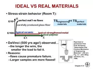
SUMMARY • Engineering materials don't reach theoretical strength. • Flaws produce stress concentrations that cause premature failure. • Sharp corners produce large stress concentrations and premature failure. • Failure type depends on T and stress: - for noncyclic s and T < 0.4Tm, failure stress decreases with: - increased maximum flaw size, - decreased T, - increased rate of loading. - for cyclic s: - cycles to fail decreases as Ds increases. - for higher T (T > 0.4Tm): - time to fail decreases as s or T increases.