2002 STIM-LAB Proppant Consortium
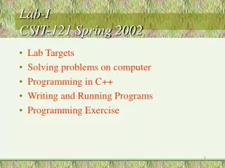
2002 STIM-LAB Proppant Consortium. July 19, 2002 San Diego, California Robert D. Barree Michael W. Conway. 4.2 - Modeling of Proppant Flowback. Original Flowback Model. Major Equations. Normalize velocity to 2 lb/ft 20/40 Lt Wt Ceramic Proppant Factor

2002 STIM-LAB Proppant Consortium
E N D
Presentation Transcript
2002STIM-LAB Proppant Consortium July 19, 2002 San Diego, California Robert D. Barree Michael W. Conway 4.2 - Modeling of Proppant Flowback
Major Equations • Normalize velocity to 2 lb/ft 20/40 Lt Wt Ceramic • Proppant Factor • Critical velocity = 0.65 cm/s* PF + CF
Flowback Predictive Model • New modeling approach suggested by: Bi-power law correlations for sediment transport in pressure driven channel flows • J. Wang, D. D. Joseph: Department of Aerospace Engineering and Mechanics, University of Minnesota, Minneapolis, MN • M. Conway, R. D. Barree • Gravity Reynolds number: • Fluid Reynolds number based on particle size
Predictive Equation • In the flowback case, three dimensionless parameters d/W, RG , and Rf, enter the power law correlation : • This conceptually represents the drag force acting on a single particle in a flow field
Application of Carreau Model • Model for proppant size effect • As approach d/W with no flowback • Flowback velocity is problematic • May not show a clear dependence on closure
Continuation Program • Design and execute experiments to clarify key parameters required for modeling effort • Example: Minimum velocity for flowback at d/W = 0.01 • Re-examine multiphase data • Examine multiphase approach • Use fractional flow • Relate capillary pressure and saturations to additional cohesion and velocity required to cause flowback • Begin to incorporate the effect of resin coated proppants