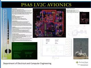
LV2 Flight Computer Carrier Board
10 likes | 129 Vues
The LV2 Rocket's PowerPC-based single board computer for avionics, compact yet powerful, with advanced features for optimal performance and data transfer in critical aerospace operations.

LV2 Flight Computer Carrier Board
E N D
Presentation Transcript
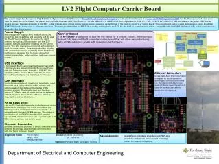
LV2 Flight Computer Carrier Board • The current Single board computer (TQM5200 from TQ) used on the LV2 Rocket is a PowerPC-based single board computer, specifically chosen because of a "Linux on POWER" grant from IBM that Dr. Massey received a few years back. Its small size (80 X 60mm) and feature load(400 MHz Freescale MPC5200 PowerPC , 64 MB SDRAM / 32 MB FLASH, Lots of peripherals: USB 1.1, CAN, UARTS, PCI, ATA/IDE, SPI, etc) makes it the perfect SBC for the Rocket Avionic. The main downside of this SBC is that it has an array of high density surface mount connectors on the bottom of the board to mount to a “carrier board.”The carrier board used is a giant multi-purpose carrier board that (STK5200) breaks it into a lots of different connectors . The main problem is that the STK5200 is too big and fragile for the LV2. So, the need for a smaller, more robust , compatible with the TQM5200 but yet fully loaded carrier board is the goal of this design project. Power Supply Switching power supply (SPS) module takes 20V input from the rocket bus and converts to 3.3V and 5V. The 5V bus is designed to supply the patch antenna through a USB connector and the 3.3V supplies the SBC and other modules on the carrier board. The SPS node is synchronized with a 500kHz clock for noise control. An active protection circuitry with automatic recovery capability from hazardous conditions is designed for the board protection against overvoltage, under-voltage, and over-current events. USB interface 2 full speed, 802.11a compatible Downstream USB 2.0 modules are designed to interface respectively with the Telemetry node through a USB 802.11a adapter and the Inertial Measurement Unit node through the multipurpose Rocketbus Connector. CAN interface Controller Area Network interfacing is added to meet the need for a highly reliable safety system and communication bus between the nodes of the Avionics system. The peer to peer bus topology nature of CANs in case of power failure for instance will not result in failure of the CAN bus, which is important in critical situations. PATA flash drive A 44 pin IDE Flash Module provides a reliable storage device that meets the challenges that hostile environment and limited space that the Avionics chamber represent. It is compatible with Standard IDE ATA interface. This module is paired with a 44 pin IDE/ATA embedded Disk card that support UDMA data transfer mode also supported by the LV2 SBC, allowing optimum data transfer speed. Ethernet Connector Ethernet connection provides a direct, low noise area network technology used for fast communication with the flight computer board. Carrier board The fc-carrier is designed to address the needs for a smaller, robust, more compact but yet fully featured flight computer carrier board that will allow easy interfacing with all other Avionics nodes with maximum performance. Ethernet Connector: A separate off-board Ethernet connector is designed for the sole purpose of optimizing the computer carrier board size. The relatively fast data transfer speed of Ethernet makes it a method of choice for communicating with the Rocket while on the ground. Capstone Team : Pierre Djinki Advisor: Andrew Greenberg Varun, ArurDr. Tymerski Takuya, Namura Sponsor: Portland State Aerospace Society Acknowledgements: Special thanks to Andrew Greenberg and PSAS who provided us with all the resources and knowledge needed to complete this project Department of Electrical and Computer Engineering