Download
1 / 1
10 likes | 136 Vues
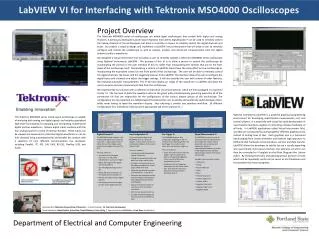
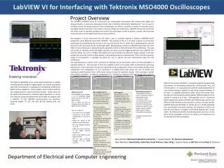
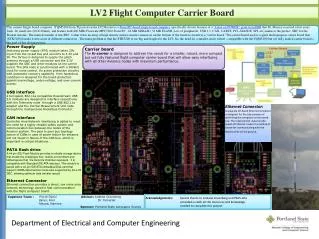
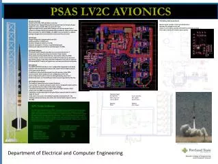
PSAS LV2C AVIONICS. APS Battery Pack Sensor Board Measure pack voltage, current and temperature Monitor the voltage on each cell Absolute and relative capacity estimated by coulomb counting Five LEDs to display the relative pack capacity. Generic Front End

E N D
PSAS LV2C AVIONICS • APS Battery Pack Sensor Board • Measure pack voltage, current and temperature • Monitor the voltage on each cell • Absolute and relative capacity estimated by coulomb counting • Five LEDs to display the relative pack capacity • Generic Front End • Consists of the SPS, HAP and Micro-controller • Switching Power Supply (SPS)converts the power from the Avionics Power Supply to a more useable 5Vdc for use by the node • Highly Available Power supply (HAP) charges and delivers power from a Lithium Ion Polymer battery providing battery backup for safety critical nodes • Micro-controller the NXP LPC2368 is an ARM7 micro-controller in a 100 pin package charged with communications and control for each node • APS Charger • Charger designed to charge batteries at 8.5A • Battery capacity is 4.25Ah each • Nominal voltage per battery of 3.7Vdc • Batteries arranged in a 4-series, 2 parallel (4s2p) pack • Battery pack capacity of 8.5Ah at rated Voltage of 14.8Vdc • APS Power Switches • The power switch network provides over-current protection for 7 downstream devices powered by the Avionics Power System • Along with protecting attached devices, the switches allow the ARM microcontroller to control and monitor which of the devices are powered • Each switch utilizes a hot-swap controller integrated circuit with an external N-Channel MOSFET which act together as a current controlled circuit breaker • APS USB hub • The SMSC USB2517 hub chip is a user configurable integrated circuit which supports USB communication between the Launch Vehicle flight computer and 7 downstream devices • In addition to the actual data signals, the hub connects to the ARM microcontroller which enables on line configuration of the hub • Some configuration options include enabling/disabling any of the 7 downstream ports, and controlling the device speed supported by the chip • APS Umbilical Connection • The umbilical connection serves several functions: • It acts similar to a lap-top computer power chord, charging the battery of the APS, and powering the rocket as the battery charges • It provides communication lines which allow the flight computer direct contact with the ARM microcontroller • It provides a rocket ready signal telling the flight computer that the rocket is ready for launch • In the event of a launch, the umbilical is pulled out during lift-off. The umbilical connection detects this event and a launch-detect signal is sent to the ARM Image provided by PSAS Capstone Team: Ai Ling Chen Scott Schuehle Mike Engstrom Ken Zeigler Jeremy Booth David Loupin Sponsor: Advisor: PSAS Allen Taylor Graphic provided by Portland State Aerospace Society – Frank Mathew Photo provided by Portland State Aerospace Society – Fred Azinger Department of Electrical and Computer Engineering