Download
1 / 51
520 likes | 757 Vues
LEGAL REQUIREMENTS P12-14 and P50-55. The Health and Safety at Work etc Act 1974 The Management of Health and Safety at Work Regulations 1999 The Provision and Use of Work Equipment Regulations 1998 The Electricity at Work Regulations 1989

E N D
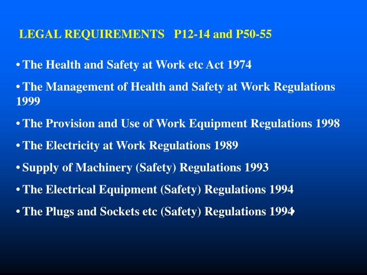
LEGAL REQUIREMENTS P12-14 and P50-55 The Health and Safety at Work etc Act 1974 The Management of Health and Safety at Work Regulations 1999 The Provision and Use of Work Equipment Regulations 1998 The Electricity at Work Regulations 1989 Supply of Machinery (Safety) Regulations 1993 The Electrical Equipment (Safety) Regulations 1994 The Plugs and Sockets etc (Safety) Regulations 1994
LEGAL REQUIREMENTS P12-14 and P50-55 The Health and Safety at Work etc Act 1974 Section2 “It shall be the duty of every employer to ensure, so far as is reasonably practicable, the health, safety and welfare at work of all his employees. ------- the matters to which that duty extends include in particular; (a) the provision and maintenance of plant and systems at work that are, so far is reasonably practicable, safe and without risks to health.”
LEGAL REQUIREMENTS P12-14 and P50-55 The Management of Health and Safety at Work Regulations 1999 Regulation 3(1) • “Every employer shall make a suitable and sufficient assessment of; • the risks to the health and safety of his employees to which they are exposed whilst they are at work, and • the risks to the health and safety of persons not in his employment arising out of or in connection with the conduct by him of his undertaking.”
LEGAL REQUIREMENTS P12-14 and P50-55 The Provision and Use of Work Equipment Regulations 1998) Regulation 4(1) “Every employer shall ensure that work equipment is so constructed or adapted as to be suitable for the purpose for which it is provided.” Regulation 5 “Every employer shall ensure that work equipment is maintained in an efficient state, in efficient working order and in good repair”
LEGAL REQUIREMENTS P12-14 and P50-55 The Electricity at Work Regulations 1989 Regulation 4(2) “As may be necessary to prevent danger, all systems, shall be maintained so as to prevent, so far as is reasonably practicable, such danger.” Regulation 2(1) defines system to include electrical equipment and then defines electrical equipment; “Electrical equipment includes anything used, intended to be used or installed for use, to generate, provide, transmit, transform, rectify, convert, conduct, distribute, control, store, measure or use electrical energy.” There are NO VOLTAGE LIMITATIONS
DESIGN AND CONSTRUCTIONAL FEATURES OF ELECTRICL EQUIPMENT P9 CONSTRUCTION CLASSES
DESIGN AND CONSTRUCTIONAL FEATURES OF ELECTRICL EQUIPMENT P9 CLASS II CLASS III SAFETY ISOLATINGTRANSFORMER
Class I construction showing basic insulation and earthed metal.
Class II equipment with a substantial enclosure of insulating material comprising basic and supplementary insulation.
Class II equipment with substantial enclosure of reinforced insulating material.
Class II equipment with substantial enclosure of insulating material – the insulation includes air.
Class II equipment with unearthed metal in the enclosure, separated from live parts by basic and supplementary insulation.
EQUIPMENT TYPES P15 PORTABLE APPLIANCE MOVEABLE EQUIPMENT HAND HELD APPLIANCES STATIONARY EQUIPMENT FIXED APPLIANCES BUILT IN EQUIPMENT IT EQUIPMENT EXTENSION LEADS
6. THE ELECTRICAL TESTS P17 THERE ARE 4 RECOGNISED TEST SITUATIONS • Type testing to an appropriate standard. • Production testing • In-service testing • Testing after repair
ELECTRICAL TESTS cont P17 6.2.1 Type Testing Type testing is carried out by test houses or manufacturers to assess compliance with a standard (British or European). The tests are usually destructive. 6.2.2 Production Testing Carried out by manufacturers during or following production to ensure that appliances are in accordance with appropriate standards.
INSPECTION REQUIREMENTS P17 6.3 In-service Inspection This is carried out as a routine to ensure that equipment remains in satisfactory condition. The tests will involve; Preliminary visual inspection. Earth continuity tests for class I equipment. Insulation testing or earth leakage measurement. Functional checks. REMEMBER, A HEALTHY PIECE OF ELECTRICAL EQUIPMENT CAN BECOME LETHAL IF THE FIXED INSTALLATION IS FAULTY!!!
INSPECTION REQUIREMENTS P18 6.4 Testing after repair. Testing after repair could use production tests or in-service tests depending on assessment by repairer. If necessary the manufacturer should be consulted. It may be appropriate to use “flash tests” in this situation. Such tests are NOT appropriate for in-service testing.
THE IN-SERVICE INSPECTION P18 Recognises 3 distinct lines of defence; THE USER CHECK FORMAL VISUAL INSPECTION COMBINED INSPECTION AND TEST
IN-SERVICE INSPECTION AND TEST; 7.3 FACTORS AFFECTING THE FREQUENCY OF INSPECTION; P 18 THE ENVIRONMENT THE USERS THE EQUIPMENT CONSTRUCTION THE EQUIPMENT TYPE
13. USER CHECKS P35 (A)Is the user aware of any faults? (B)Disconnect equipment if possible before inspecting. (C)Inspect the equipment; look at the FLEX, the PLUG, the SOCKET OUTLET or FLEX OUTLET, the APPLIANCE, the ENVIRONMENT, the SUITABILITY FOR THE JOB.
13 USER CHECKS CONTINUED FAULTY EQUIPMENT FAULTY EQUIPMENT MUST BE; Switched off and unplugged from supply Labelled to identify that it must not be used Reported to the responsible person
14. FORMAL VISUAL INSPECTION WILL ASSESS 5 DISTINCT AREAS P37 - 39 14.1 THE ENVIRONMENT 14.2 GOOD HOUSEKEEPING 14.3 SUITABILITY OF THE EQUIPMENT 14.4 DISCONNECTION OF EQUIPMENT 14.5 THE CONDITION OF THE EQUIPMENT
FORMAL VISUAL INSPECTION A formal visual inspection of electrical equipment should review the following; 14.1 THE ENVIRONMENT – is it abnormally harsh or hazardous. Mechanical damage Ingress of moisture High and low temperatures Flammable or explosive atmosphere. Dirty or corrosive conditions.
FORMAL VISUAL INSPECTION 14.2 GOOD HOUSEKEEPING Cables are not located where they might be damaged or create a trip hazard. Isolation or disconnection is readily accessible. Adequate space for cooling and ventilation. Cups. plants etc are not set on electrical equipment equipment. Cord is not damaged by equipment pushed too close to wall etc. Equipment is operated with protective covers in place, doors closed. No indiscriminate use of multi-way adaptors.
FORMAL VISUAL INSPECTION 14.3SUITABILITY OF EQUIPMENT Is the equipment suitable for the task it is being asked to do? Consider environment into which the equipment might be brought. Consider the effects of the normal function of the equipment on itself. Will it generate dust, water, heat, fumes, arcing etc?
FORMAL VISUAL INSPECTION 14.4DISCONNECTION OF EQUIPMENT An assessment needs to be made to ensure that the means of disconnection from the supply is readily available; For normal functional use. In Emergency. To carry out maintenance.
FORMAL VISUAL INSPECTION: 14.5 Condition of equipment The Flexible cable; Is it in good condition, free from cuts, fraying or damage? Is it properly located to avoid damage and trips? Is it too long, too short or otherwise unsatisfactory? Is it properly secured to the plug and appliance? The Socket or Flex outlet; Is it free from signs of overheating, damage or cracks? The Appliance; Does it work? Does it switch off properly? Is it free from cracks and damage to the case which could lead to access to live parts? Can it be used safely?
FORMAL VISUAL INSPECTION 14.5 continued The Plug Is it approved and appropriately durable? Are the pins sleeved (required from The Plugs and Sockets etc (Safety Regulations) 1994 and not retrospective). Is there any sign of damage to the pins or plug body? Is there any sign of overheating? Is the body properly secured? Is the fuse to BS1362 and appropriate to the rating of the appliance? Is the flex secure and fully “home”? If the plug can be opened, are the terminations correctly made with correct polarity? Ensure that there is no excessive removal of insulation, there are no loose strands and that there is no undue strain or compression damage on the conductors.
NOW COMPLETE THE QUESTIONS ON PAGES FIVE to SEVEN IN THE WORKBOOK
OVERVIEW OF INSPECTION ANDTESTING By far, the most important aspect of inspection and testing is; The Visual Inspection This is supplemented by testing if necessary. The tests will include; An earth continuity test for class I equipment. An insulation resistance test ( or an earth leakage test ) A functional test sometimes performed as a load test.
15. COMBINED INSPECTION AND TEST P40 Determine whether equipment can be disconnected from supply. Disconnect only after permission is sought. Establish the type, rating and class of the equipment. The user of the equipment may have useful information. Thoroughly inspect the appliance for signs of damage. Inspect the flexible cable throughout its length for signs of damage. Inspect the plug. NB. A resilient plug marked BS1363 A may be required if the plug is subject to harsh treatment, for example, vacuum cleaners, lawnmowers and extension leads. Assess if the equipment is suitable for the environment. Assess if the equipment is suitable for the task it is being asked to do.
15.4 EARTH CONTINUITY TESTING P42 • LOW CURRENT TEST ( 20mA to 200Ma ) • HIGH CURRENT TEST ( 1.5 X rating of fuse up to 25amps for a period between 5 and 20 secs) • Note; Max value 0.1 + R ohms
15.5 and 15.6 INSULATION RESISTANCE TESTS P 43 • INSULATION RESISTANCE AT 500V dc • TOUCH CURRENT METHOD • NOTE; Minimum and maximum values are given in • TABLE 2 and TABLE 3
15.7 FUNCTIONAL TESTS P45 ESSENTIALLY THIS TEST IS JUST TO ENSURE THAT THE EQUIPMENT IS WORKING PROPERLY. IT MAY CONSIST OF A LOAD TEST. ( Available on many PAT testers )
NOW COMPLETE PAGE 8 TO PAGE 12 (up to Labelling) IN YOUR WORKBOOK
8.2 DOCUMENTATION P22 and Appendix 5 The EAW Regulations do not require records, however it would be difficult to demonstrate compliance without them. All areas subject to the EAW Regulations should carry out inspections and record results in accordance with approved methods. It is prudent for inspectors of electrical equipment to call a duty holders attention to the need for regular inspection and testing of the fixed installation. Note; Regulation 6 of PUWER requires records to be kept
LABELLING EQUIPMENT MUST BE UNIQUELY IDENTIFIABLE MUST HAVE CURRENT SAFETY STATUS RE-TEST DATE MUST BE CLEAR
15.8 DAMAGED OR FAULTY EQUIPMENT P45 SHOULD BE BROUGHT TO THE ATTENTION OF THE RESPONSIBLE PERSON
15.10 EXTENSION LEADS. P46 Should be treated as class I appliances 2 core leads should be removed from service. Code of Practice for the In-service inspection and Testing of Electrical Equipment issued by the IEE recommends restricting their length or otherwise fit with a residual current device. Consider the maximum values set out on P46
8.2 THE DOCUMENTATION P22 The following documentation should be established and maintained; A Register of all Equipment (Va) A Record of formal and combined inspections (Vb) A Repair Register (Vd) A Register of Faulty Equipment (Ve) A Status Label (Vc)