Download
1 / 21
220 likes | 277 Vues
Outline of muon track reconstruction, tagging efficiency, position resolution, and angle differences between true and reconstructed tracks. Background on muon-induced neutron background and rejection methods. Results of vertex resolution using PMTs. Improved muon tracking algorithm and optimization needed.

E N D
Muon reconstruction at RENO 전은주, 강운구, 김영덕, 마경주 (세종대학교), 공대정,김동희,김우영,사무엘스테파냔, 서준석,아딜 칸,안드레이 김 (경북대학교), 박인곤 (경상대학교), 박명렬 (동신대학교), 안정근, 이효상(부산대학교), 김수봉,김현수,박강순,박정식,신경하,이재승,최선호,황원석 (서울대학교), 권은향,김동현,박차원,백승록,유인태,최수용,최영일 (성균관대학교), 김성현,김재률,주경광,임인택,장지승,정신석 (전남대학교), 오영도 (포항공과대학교), N.Danilov,YU.Krylov,G.Novikova,E.Yanovich (INR and IPCE, Russia) KPS 한국물리학회 Apr. 18, 2008
Outline • Muon track reconstruction • Tagging efficiency • Position resolution • Difference in angles between tracktrue and trackrec • Summary
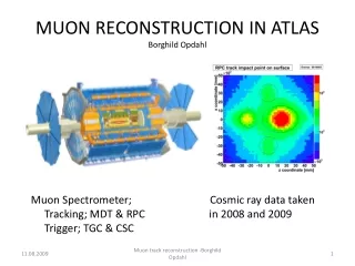
Background – why do we need muon tagging? • Correlated background • Muon induced neutron background: cosmic muons produce neutrons in the target region via spallation and muon capture. • Neutrons through going muon: muons intersect the detector and should be indentified by the veto system • Neutrons stopping muon: negative muons stopped in the target region can be captured by nuclei where a neutron is released afterward • Beta-neutron cascades: muon spallation on 12C nuclei in the organic liquid scintillator may generate 8He, 9Li, and 11Li which may undergo beta decay with a neutron emission even if they are tagged by the veto system they can live long enough such that their decay cannot be associated with the last tagged muon. • Uncorrelated background • Radioactivity due to PMTs • Radioactivity due to detector materials • Radioactivity from rock • Single neutron events induced by cosmic muons
Muon tagging for rejecting the muon induced neutron background (a) muon (c) muon (b) muon (a) neutrons produced by mouns that pass through the LS (b) neutrons produced in the buffer (c) neutrons produced in the veto
Muon track reconstruction • Muons pass through the detector • Scintillation photons along the entire path in scintillator. • Scintillation photons travel isotropically from the muon track • Cerenkov photons in the buffer oil and scintillator. • Cerenkov photons are produced at an angle, theta, relative to the muon tracking • The earliest to hit a particular PMT come from the muon track at the same angle as the cherenkov photons. • Using the first photons to arrive at a PMT allow us to use the same model (light propagation) for cherenkov and scintillation photons. • Muon track entrance and exit points • Muon track entrance is estimated from the PMT with the earliest photon hit • Exit point can be determined by using the PMT with the highest number of photoelectrons
photoelectrons Photon hit time distribution (ns) Using OD PMTs Using ID PMTs
Muon tagging efficiency (need to check with high statistics) • top incident: 609 (topbottom:479, topside:130) • side incident: 391 (Sidebottom:142, sideside:249)
Results of vertex resolution (using OD pmts, side side events only)
Results of vertex resolution (using ID pmts)
A ~140cm Veto (OD) B ~40cm Buffer (ID) C ~120cm D Difference in angles between tracktrue and trackrec • Muon tracking • Difference in angles (between tracktrue and BDrec)
Difference in angles between trktrue and rec with four categories BD top bottom top side Difference in angles Difference in angles side bottom side side Difference in angles Difference in angles
Summary • Muon track reconstruction (very preliminary) • Tagging efficiency • 100% using 1000 events (Need to check with high statistics !!) • Position resolution • Using ID pmts: RMS of ~70cm (entrance), RMS of ~60cm (exit) • Using OD pmts: RMS of ~20cm (entrance), RMS of ~170cm (exit) • Muon Difference in angles between tracktrue and trackrec • Muon tracking with entrance from ID pmts and exit from OD pmts • difference in angles between tracktrue and trackBD: mean of 4.3 degree, rms of 3.2 • need to improve the algorithm • need to optimize the arrangement of OD pmts
Muon (m-) events: 100 events generated • Position (0, 0, 4750mm) • Momentum (0, 0, -20GeV) OD PMT Top: pmt #541 (black histogram) Bottom: pmt #580 (black histogram) Top: pmt #537 (red histogram) Bottom: pmt #587 (red histogram) 1000 mm pmt #549 (black histogram) 0 mm pmt #558 (red histogram) -1000 mm pmt #569 (blue histogram)
Ring index (top: 0 – 4) Ring indes (side: 5 – 15) Ring index (bottom: 16 – 20) ID PMT m-
photoelectrons Photon hit time distribution (ns) Using OD PMTs Top Side Bottom
Photon hit time distribution (ns) photoelectrons Using ID PMTs Top Side Bottom
Layout of OD PMT Top: 10’’ 15 pmts 10’’ 67 pmts in total r2 r1=1558 r1 r2=3117 Side: 10’’ 36 pmts Z=3723 r Z= 2792 r= 3523 Z= 931 Z= -931 Z= -2793 Bottom: 10’’ 16 pmts
Muon Tracks (II): energy of 20 GeV m- yz xz radius xy
photoelectrons Photon hit time distribution (ns) Using OD PMTs Using ID PMTs