Download
1 / 7
70 likes | 87 Vues
Learn how to identify and fix issues with backlight inverter power supplies, covering common symptoms like dead outputs, low or missing outputs, momentary output, and more. Follow detailed troubleshooting steps for effective solutions.

E N D
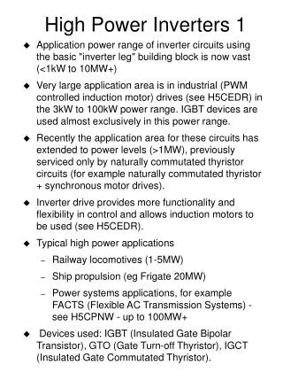
Inverter power supply symptoms can be typically broken down into the following categories: 1. All Outputs Normal: 2. All Outputs Dead (no output): 3. One Output Low or Missing – Others Normal: 4. All Outputs - Momentary Output 5. Momentary Normal Output one Inverter Side – Other Side No or Low Momentary Output:
Troubleshooting Backlight Inverter Power Supply If all outputs show normal on the SC3100 with resistive loads,k the backlight inverter supply is working. If the display exhibits inverter or CCFL symptoms reconnect the CCFL bulbs on one side of the inverter and then the other checking for normal output from the inverter with the SC3100. A problem when connecting CCFL bulbs indicate multiple bad or a shorted CCFL bulb which is shutting down the inverter. If the inverter outputs with the bulbs connected increment the brightness control through its range and monitor the output for PWM shaping by viewing the SC3100 waveform. Normal output and brightness control indicate the backlight supply is working. If the brightness control is not varying the brightness or causing a PWM shaping of the output waveform, test the brightness control input voltage to the inverter input. If it ranges normally, the brightness control circuit of the backlight inverter is defective. If the voltage does not change normally, the microprocessor control or cabling to the inverter is defective.
Troubleshooting Backlight Inverter Power Supply All Outputs Dead (no output): If all the outputs are missing, it is likely that the backlight inverter is missing an input or has a defect in the controller IC common to both output sides. Check the input DC voltage, switch input voltage and brightness control input voltage to the inverter board. If any or all are missing or abnormal the microprocessor/control circuit board or cabling from this circuit board is bad. If all inputs are normal check the DC voltage after the fuse(s). If the voltage is low or missing, the fuse is open. If normal, check the voltage, IC oscillator, and drive outputs from the IC as an IC or IC component is likely defective. One Output Low or Missing – Others Normal: This is an unusual symptom as multiple outputs on one side of the inverter share the controller IC, driver, royer oscillator and transformer. Double check the output to be sure. If one output is bad, the problem must be with the series output capacitor, connector or circuit connections to that output.
Troubleshooting Backlight Inverter Power Supply All Outputs - Momentary Output Momentary output(s) is common among backlight inverter symptoms but not to all outputs. A momentary output to all outputs with proper resistive substitute loads suggest the control IC, drivers, royer oscillators, transformers, series output capacitors are all good. The problem is likely a protection shutdown that is unwarranted. The likely cause is a problem in one of the current sense feedbacks or in an over-voltage shutdown protect circuits. Troubleshooting this defect requires measuring the momentary voltages as you turn on the display and output is present for that brief moment. Measure the DC voltage on the DC return test points. Normal voltage suggests a defect in the comparator amplifier section of the control IC or related components. The voltage should rise up to several volts while the output waveform is present. If not, a defect exists in the ground return resistor, diodes, or filter capacitors preventing DC voltage feedback an indication of normal CCFL current flow. Measure for a waveform at the ground return point of the CCFL bulbs to determine where the open is in the DC feedback path. isolate the defect.
Troubleshooting Backlight Inverter Power Supply Momentary Normal Output One Inverter Side – Other Side No or Low Momentary Output: An output from one inverter side and not the other is a common symptom. It indicates that a problem exist in the driver, royer oscillator or, transformer on that side of the backlight inverter. Measurements must be made by repeatedly applying voltage to the inverter while you measure momentary waveforms or voltages. Check for the normal waveform at the AMP test points to see if the oscillator is starting and oscillating. A normal momentary waveform indicates a bad transformer or secondary capacitor or connector. No waveform indicates an oscillator defect, driver stage defect or bad IC output. Measure for a momentary waveform at the driver transistor to further isolate the defect.
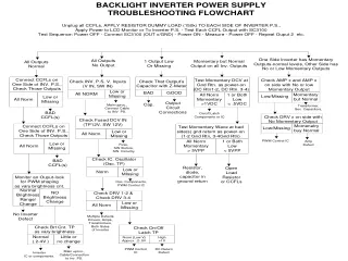
Troubleshooting Backlight Inverter Power Supply Procedure: Switch the PR570 CURRENT/POWER Switch to “TRIP RESET.” Set a Trouble Switch to the “BAD” position as directed by the instructor. Switch the CURRENT/POWER Switch to “CURRENT.”. Trouble Switch #: 2 Perform the first step in the Backlight Inverter Power Supply Troubleshooting FlowChart. APPLY RESISTOR DUMMY LOAD (150k) TO EACH SIDE OF INVERTER P.S., Apply Power to LCD Monitor or To Inverter P.S. - Test Each CCFL Output with SC3100 Test Sequence: Power OFF - Connect SC3100 (OUT x/Gnd Rtn) - Power ON - Measure - Power OFF - Repeat Determine which symptom in the flowchart accurately describes the symptom of the backlight inverter supply based upon output testing. Record the results/symptom(s). Symptom: ______________________________ 4. Match the symptoms to the appropriate section of the flowchart. 5. Follow the flowchart making measurements as directed until the problem is isolated. Record your steps/measurements and results/conclusions below. 6. Record the suspect stage and/or components. Troubleshooting Step 1: __________________________Result: _____________________ Troubleshooting Step 2: ___________________________Result:______________________