Chapter 10 ETCHING
Chapter 10 ETCHING. CONTENTS. Introduction Basic Concepts Wet etching Plasma etching Manufacturing Methods Plasma etching conditions and issues Plasma etch methods for various films Measurements Methods Models and Simulations Limits and Future Trends. Introduction.


Chapter 10 ETCHING
E N D
Presentation Transcript
CONTENTS • Introduction • Basic Concepts • Wet etching • Plasma etching • Manufacturing Methods • Plasma etching conditions and issues • Plasma etch methods for various films • Measurements Methods • Models and Simulations • Limits and Future Trends
Introduction • After a thin film is deposited, it is usually etched to remove unwanted materials and leave only the desired pattern on the wafer • The process is done many times(review flow chart of Chapter 2) • An overview of the process is shown in Figure 10-1 • In addition to deposited films, sometimes we also need to etch the Si wafer to create trenches (especially in MEMS) • The masking layer may be photoresist, SiO2 or Si3N4 • The etch is usually done until another layer of a different material is reached
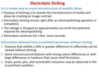
Introduction • Etching can be done “wet” or “dry” • Wet etching • uses liquid etchants • Wafer is immersed in the liquid • Process is mostly chemical • Wet etching is not used much in VLSI wafer fab any more
Introduction • Dry etching • Uses gas phase etchants in a plasma • The process is a combination of chemical and physical action • Process is often called “plasma etching” • This is the normal process used in most VLSI fab • The ideal etch produces vertical sidewalls as shown in 10-1 • In reality, the etch occurs both vertically and laterally (Figure 10-2)
Introduction • Note that • There is undercutting, non-vertical sidewalls, and some etching of the Si • The photoresist may have rounded tops and non-vertical sidewalls • The etch rate of the photoresist is not zero and the mask is etched to some extent • This leads to more undercutting
Introduction • Etch selectivity is the ratio of the etch rates of different materials in the process • If the etch rate of the mask and of the underlying substrate is near zero, and the etch rate of the film is high, we get high selectivity • This is the normally desired situation • If the etch rate of the mask or the substrate is high, the selectivity is poor • Selectivities of 25 – 50 are reasonable • Materials usually have differing etch rates due to chemical processes rather than physical processes
Introduction • Etch directionality is a measure of the etch rate in different directions (usually vertical versus lateral)
Introduction • In isotropic etching, the etch rates are the same in all directions • Perfectly anisotropic etching occurs in only one direction • Etch directionality is often related to physical processes, such as ion bombardment and sputtering • In general, the more physical a process is, the more anisotropic the etch is and the less selective it is • Directionality is often desired in order to maintain the lithographically defined features
Introduction • Note, however, that very anisotropic structures can lead to step coverage problems in subsequent steps • Selectivity is very desirable • The etch rate of the material to be removed should be fast compared to that of the mask and of the substrate layer • It is hard to get good directionality and good selectivity at the same time
Introduction • Other system requirements include • Ease of transporting gases/liquids to the wafer surface • Ease of transporting reaction products away from wafer surface • Process must be reproducible, uniform, safe, clean, cost effective, and have low particulate production
Basic Concepts • We consider two processes • “wet” etching • “dry” etching • In the early days, wet etching was used exclusively • It is well-established, simple, and inexpensive • The need for smaller feature sizes could only be met with plasma etching • Plasma etching is used almost exclusively today
Basic Concepts • The first wet etchants were simple chemicals • By immersing the wafer in these chemicals, exposed areas could be etched and washed away • Wet etches were developed for all step • For SiO2, HF was used. • Wet etches work through chemical processes to produce a water soluble byproduct
Basic Concepts • In some cases, the etch works by first oxidizing the surface and then dissolving the oxide • An etch for Si involves a mixture of nitric acid and HF • The nitric acid (HNO3) decomposes to form nitrogen dioxide (NO2) • The SiO2 is removed by the previous reaction • The overall reaction is
Basic Concepts • Buffers are often added to keep the etchants at maximum strength over use and time • Ammonium fluoride (NH4F) is often used with HF to help prevent depletion of the F ions • This is called Basic Oxide Etch (BOE) or Buffered HF (BHF) • The ammonium fluoride reduces the etch rate of photoresist and helps eliminate the lifting of the resist during oxide etching • Acetic acid (CH3COOH) is often added to the nitric acid/HF Si etch to limit the dissociation of the nitric acid
Basic Concepts • Wet etches can be very selective because they depend on chemistry • The selectivity is given by • Material “1” is the film being etched and material”2” is either the mask or the material below the film being etched • If S>>1, we say the etch has good selectivity for material 1 over material 2
Basic Concepts • Most wet etches etch isotropically • The exception is an etch that depends on the crystallographic orientation • Example—some etches etch <111> Si slower than <100> Si • Etch bias is the amount of undercutting of the mask • If we assume that the selectivity for the oxide over both the mask and the substrate is infinite, we can define the etch depth as “d” and the bias as “b”
Basic Concepts • We often deliberately build in some overetching into the process • This is to account for the fact that • the films are not perfectly uniform • the etch is not perfectly uniform • The overetch time is usually calculated from the known uncertainties in film thickness and etch rates • It is important to be sure that no area is under-etched; we can tolerate some over-etching
Basic Concepts • This means that it is important to have as high a selectivity as possible to eliminate etching of the substrate • However, if the selectivity is too high, over-etching may produce unwanted undercutting • If the etch rate of the mask is not zero, what happens? • If m is the amount of mask removed, we get unexpected lateral etching
Basic Concepts • m is called “mask erosion” • For anisotropic etching, mask erosion should not cause much of a problem if the mask is perfectly vertical • Etching is usually neither perfectly anisotropic nor perfectly isotropic • We can define the degree of anisotropy by
Basic Concepts • Isotropic etching has an Af = 0 while anisotropic etching has Af = 1 • There are several excellent examples in the text that do simple calculations of these effects • These examples should be studied carefully
Example • Consider the structure below • The oxide layer is 0.5 m. Equal structure widths and spacings, Sf, are desired. The etch anisotropy is 0.8. • If the distance between the mask edges, x, is 0.35 m, what structure spacings and widths are obtained?
Example • To obtain equal widths and spacings, Sf, the mask width, Sm, must be larger to take into account the anisotropic etching • Sincewhere b is the bias on each side, and • Since • Thus
Example • This result makes sense • For isotropic etching, Af=0 and Sm is a maximum • For perfectly anisotropic etching, Af=1 and Sm=Sf and is a minimum • The distance between the mask edges (x) is the minimum feature size that can be resolved • But • Substitution and rearranging yields (note typo in text)
Example • Substituting numbers for the problem • This result shows that the structure size can approach the minimum lithographic dimension only when the film thickness gets very small OR as the anisotropy gets near 1.0 • Very thin films are not always practical • This means we need almost vertical etching • Wet etching cannot achieve the desired results
Plasma Etching • Plasma etching has (for the most part) replaced wet etching • There are two reasons: • Very reactive ion species are created in the plasma that give rise to very active etching • Plasma etching can be very anisotropic (because the electric field directs the ions) • An early application of plasma etching (1970s) was to etch Si3N4 (it etches very slowly in HF and HF is not very selective between the nitride and oxide)
Plasma Etching • Plasma systems can be designed so that either reactive chemical components dominate or ionic components dominate • Often, systems that mix the two are used • The etch rate of the mixed system may be much faster than the sum of the individual etch rates • A basic plasma system is shown in the next slide
Plasma Etching • Features of this system • Low gas pressure (1mtorr – 1 torr) • High electric field ionizes some of the gas (produces positive ions and free electrons) • Energy is supplied by 13.56 MHz RF generator • A bias develops between the plasma and the electrodes because the electrons are much more mobile than the ions (the plasma is biased positive with respect to the electrodes)
Plasma Etching • If the area of the electrodes is the same (symmetric system) we get the solid curve of 10-8 • The sheaths are the regions near each electrode where the voltage drops occur (the dark regions of the plasma) • The sheaths form to slow down the electron loss so that it equals the ion loss per RF cycle • In this case, the average RF current is zero
Plasma Etching • The heavy ions respond to the average voltage • The light electrons respond to the instantaneous voltage • The electrons cross the sheath only during a short period in the cycle when the sheath thickness is minimum • During most of the cycle, most of the electrons are turned back at the sheath edge • The sheaths are thus deficient in electrons • They are thus dark because of a lack of light-emitting electron-ion collisions
Plasma Etching • For etching photoresist, we use O2 • For other materials we use species containing halides such as Cl2, CF4, and HBr • Sometimes H2, O2, and Ar may be added • The high-energy electrons cause a variety of reactions • The plasma contains • free electrons • ionized molecules • neutral molecules • ionized fragments • Free radicals
Plasma Etching • In CF4 plasmas, there are • Free electrons • CF4 • CF3 • CF3+ • F • CFand F are free radicals and are very reactive • Typically, there will be 1015 /cc neutral species and 108-1012 /cc ions and electrons
Plasma Etching Mechanisms • The main species involved in etching are • Reactive neutral chemical species • Ions • The reactive neutral species (free radicals in many cases) are primarily responsible for the chemical component • The ions are responsible for the physical component • The two can work independently or synergistically
Plasma Etching Mechanisms • When the reactive neutral species act alone, we have chemical etching • Ions acting by themselves give physical etching • When they work together, we have ion-enhanced etching
Chemical Etching • Chemical etching is done by free radicals • Free radicals are neutral molecules that have incomplete bonding (unpaired electrons) • For example • Both F and CF3 are free radicals • Both are highly reactive • F wants 8 electrons rather than 7 and reacts quickly to find a shared electron
Chemical Etching • The idea is to get the free radical to react with the material to be etched (Si, SiO2) • The byproduct should be gaseous so that it can be transported away (next slide) • The reaction below is such a reaction • Thus, we can etch Si with CF4 • There are often several more complex intermediate states
Chemical Etching • Gas additives can be used to increase the production of the reactive species (O2 in CF4) • The chemical component of plasma etching occurs isotropically • This is because • The arrival angles of the species is isotropic • There is a low sticking coefficient (which is more important) • The arrival angle follows what we did in deposition and there is a cosn dependence where n=1 is isotropic
Chemical Etching • The sticking coefficient is • A high sticking coefficient means that the reaction takes place the first time the ion strikes the surface • For lower sticking coefficients, the ion can leave the surface (usually at random angles) and strikes the surface somewhere else
Chemical Etching • One would guess that the sticking coefficient for reactive ions is high • However, there are often complex reactions chained together. This complexity often means low sticking coefficients • Sc for O2/CF4 on Si is about 0.01 • This additional “bouncing around” of the ions leads to isotropic etching
Chemical Etching • Since free radicals etch by chemically reacting with the material to be etched, the process can be highly selective
Physical Etching • Due to the voltage drop between the plasma and the electrodes and the resulting electric field across the sheaths, positive ions are accelerated towards each electrode • The wafers are on one electrode • Therefore, ionic species (Cl+ or Ar+) will be accelerated towards the wafer surface • These ions striking the surface result in the physical process • The process is much more directional because the ions follow the field lines