Digital Design and Synthesis COEN 6501
620 likes | 1.61k Vues
Digital Design and Synthesis COEN 6501. Lecture_1 In this lecture we will review: The Digital Design process Introduce and review Adders The Carry Ripple Through Adder The Carry Look Ahead Adder. System Design Description. Systems are described in terms of three domains:

Digital Design and Synthesis COEN 6501
E N D
Presentation Transcript
Digital Design and Synthesis COEN 6501
Lecture_1 • In this lecture we will review: • The Digital Design process • Introduce and review Adders • The Carry Ripple Through Adder • The Carry Look Ahead Adder
System Design Description Systems are described in terms of three domains: Behavioural domain Structural domain Physical domain
Logic Synthesis Structural Behavioural Physical Synthesis Physical
Logic synthesis System Structural Behavioural Algorithmic Processor Systems Micro architecture Hardware modules Algorithms Logic Register transfer ALU, registers Circuit Logic Gates, F/Fs Transfer function Transistors Physical synthesis Rectangles Cells Macro-cells Modules Chips, boards… Physical
Expected power savings in logic synthesis at various levels of design flow Level Transformation Expected Power Saving Algorithmic Algorithm selection Orders of magnitude Behavioural Concurrency Several times Register Transfer Level Structural transformations ~10 - 15% Clock control ~10 - 90% Data/signal encoding ~20% Technology independent Extraction/decomposition ~15% Technology dependant Technology mapping ~20% Gate sizing ~20% Layout Placement 20% Optimization Levels
System Specification Design Process: It starts with behavioural description, decomposing the high level of constructs into more precise functional units, then mapping these units into physical elements. Architectural Design (behavioural) Analysis Design Implementation (structural) Analysis Design Implementation (Physical) Analysis
Design Strategies • Hierarchy • A repeated process of dividing large modules into smaller sub-modules until the complexity of sub-modules are at an appropriately comprehensible level of detail. • Parallel hierarchy is implemented in all domains.
A Structured Design • Regularity • Divide the hierarchy in to similar building blocks whenever possible. • Some programmability could be added to achieve regularity. • Modularity • Well defined behavioural, structural and physical interface. • Helps: divide tasks into well defined modules, design integration, aids in team design. • Locality • Internals of the modules are unimportant to any exterior interface.
System Design Methodology • Market windows • System features & requirements • Standards Market Analysis • Functional • Electrical • Mechanical • Environmental System Specifications • Strategies • Modelling • Verification System Architecture • Dictated by complexity, I/O pins, off-the- • shelf components, special requirements • Partitioning guidelines • Partitioning approaches: vertical, • horizontal, functional, performance System Partitioning
Strategies, chip testing, board • testing • Testability features • Penalties Testability • Dictated by: speed, power • dissipation, driving capability, • cost, lead time Technology Selection • Logic design/synthesis • Optimization • Verification Detailed Design • Off-the-shelf ICs • Application Specific ICs Implementation
Decide on packaging technical components • Design/manufacture • Components • Electrical/mechanical assembly • Mechanical assembly & components sales Assembly • Functional • DC test • AC test • Burn-in Testing • Technical documents • H/W & S/W & mechanical • User manual • Test document Documentation Production
IC Design Methodology • Requirement specification • most important function which impacts the ultimate success of an IC relates to how firm and clear the device specifications are. • Device specification may be updated throughout the design cycle. • Main items in the specifications are: • functional intent: brief description of the device, the technology and the task it performs. • Packaging specification • device port number • package type, dimension, material
Verify at every step MEMORY CPU Structural Functional Logic Circuit Layout Device
Functional Description • Functional description • high-level block diagram: all major blocks including intra block connections and connections to pin-outs indicating direction and signal flow. • Intra block signal function: description of how blocks interact with each other supported with timing diagram where necessary. • Internal block description of internal operation of each block. Where necessary, the following to be included: timing diagram, state diagram, truth table.
Specifications • I/O specifications • pin-out diagram • I/O functional description • loading • ESD requirements • latch-up protection • D.C. specifications • absolute maximum ratings for: supply voltage, pin voltages • main parameters: VIL and VIH for each input, VOL and VOH for each output, input loading, output drive, leakage current for tri-state operation, quiescent current, power-down current (if applicable)
Specification, continued • AC specifications • inputs: set-up and hold times, rise and fall times • outputs: propagation delays, rise and fall times, relative timing • critical thinking • Environmental requirements • operating temperature, storage temperature, humidity condition (if applicable) • Testing
Device Specification • Functional intent: briefly describe the device, the technology, and the circuits it will replace as well as the task it will perform. • Design concept • pin-out diagram: describe the device using a block diagram of the external view of the chip - basically, a box with all the I/O pins labelled and numbered • I/O description: use a chart to define the I/O signals shown in the pin-out diagram
Functional Specification • internal block diagram: draw blocks for major functions, show all connections including: connection to all pin-outs, connections between blocks, and direction of signal flow • Inter-block signal function: describe how the blocks interact with each other and support this with timing diagrams where necessary • internal block description: describe the internal operation of each block. When necessary, include: timing diagrams, state diagrams, and truth table • Logic description: circuit schematic or logic diagram using standard cell library components • Package description: device port number, package type, dimensions, materials
Operating characteristics Absolute maximum stress ratings. Example:
Requirements • Operating power and environmental requirement: • power supply voltage • operating supply current (specify conditions, e.g., power up, power down, frequency, output conditions) • storage temperature • operating temperature • humidity conditions (if applicable)
Input characteristics. Example chart:(V reference is VSS = 0, temperature range is 0oC to 70oC)
Output Interface CharacteristicsExample chart: (VSS = 0, T range 0oC to 70oC
AC descriptionTiming diagram: include well-labelled signal drawings of all significant input and output relationships, rise and fall times, data set-up and hold times. Indicate the voltage range over which timing must be guaranteed Definitions: VIH VIL Cout Set-up hold VIH input VIL output hold
Example: timing diagram and chart t16 RXCK t19 t20 RXFRM t22 t18 t17 RXIN t21
Critical Path • Signal paths with ‘tight’ timings (if applicable) • potential ‘race’ conditions (if applicable) • any set of paths with the same source and destination such as a clock signal and its complement (if applicable)
Test Description • Test strategy: written description of functions to be tested. This section is a guide for determining and explaining simulation patterns • simulation input/output patterns: timing diagrams which include stimulus to be applied to input pins and the expected response on the output pins
Example : Multiplicand = 100010012 = 8916 Multiplier = 101010112 = AB16 Expected Result = 1011011100000112 =5B8316
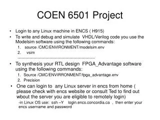
System Level Design • Top down approach • Using behavioural constructs, top level architecture is defined • Design validation is technology independent • Use HDL to model the design (e.g., VHDL and Verilog) • RTL is efficient for describing data flow
System Level design (Continued) • Timing verification is difficult unless structure logic is defined • VHDL representation can be changed into structural logic through - manual design, design synthesis: automated process which involves the conversion of VHDL/RTL into a set of registers and combinational circuits
AIMs • What the CUSTOMER wants • High Quality • Low Cost • Small Size/Weight • What the EMPLYERwants • Design the: • Best • Cheapest • In shortest time • Follow the Spec or better. • What you CHIP DESIGNER should do: • Design a chip with: • High speed • Small area • Low power • Testable and reliable • Delivered in a short time
Logic Design • Evaluation of library constructs (basic & macro) function, timing, area • Logic minimization • NAND/NOR transformation • Buffering • Fan-out reduction • Fan-in reduction
Logic Level design (Continued) • Critical timing • Priority routing • I/O compatibility • Logic optimization • Cost function: area, speed, power, or a combination
Logic Simulation • Simulation is the process of exercising a theoretical model of the design as a function of time for some applied input sequence • Logic simulation is to aid in verification of a digital system
Logic Simulation (Continued) • Components • models: functional, timing • connectivity: a description of how the basic components are connected together • stimulus: 1’s and 0’s that are applied at specific times to the primary inputs of the design • simulation control • States: basic (0, 1, X), strength could be combined with basic; strong (S), resistive (R), high impedance (Z), indeterminate (I)
Simulation model - logical *************************************************** ** Library: ACME ** Technology: 2u CMOS ** Part: fdrc ** ** Description: D flip-flop with rising edge, async. Clear *************************************************** model fdrc: table input d, rn; edge_sense input cp; output q, qn;
State_table rn, cp, d, q :: q, qn; ***** ------------------------------------------------------------ 0, (??), ?, ? :: 0, 1, 1, (01), ?, ? :: (d), !(d); 1, (?0), ?, ? :: N, !(q); 1, (1?), ?, ? :: N, !(q); end (fdrc: table);
Timing Verification • Process of making accurate delay prediction and to detect timing violation in the design. These violations include set-up time, hold time, races and spikes. • Delay through the circuit is a function of: • intrinsic delay • number of loads connected to each net • temperature • voltage • process variation, layout • Typically, best and worst case scenarios should be considered.
Simulator uses a set of equations to calculate exact delays • Fan-out • td = t(int) + K*L • t(int) = intrinsic delay • K = drive factor • L = sum of equivalent loads
Timing Verification (Continued) • temperature td = td/FT FT = (T2/T1) -M • voltage t’d = td/[VDDr(1 + 0.0f)] • process t’d = td(1 + 0.01Fp), Fp = = processing variation factor • layout information is normally supplied in two forms: • pre-layout estimation • post-layout: back annotation
Timing • hazards • spikes: inertial and transport delays • set-up time/hold time/minimum pulse width inertial tPLH = 2 tPHL = 1 transport
Timing • Critical path analysis • detection of timing violation for data path structure • the process is simply adding up path delays and compute the result with the period of the clock at the destination (F/F) • path analysis is not simulation and does not utilize information about the functionality of the device • look for two parameters • hold slack = clock period - hold path time • set up slack = clock period - set up path time • slack >= 0 • paths are chosen to provide the least amount of available set up or hold times
Structural layout synthesis • Floor planning • it is the exercise of arranging blocks of layout within a chip to minimize area or to maximize speed • floor plan editors provide graphical feedback about the size and placement of modules (without showing details), also the connectivity information between the modules in the form rat’s-not • floor planning could be done manually, or automatically with manual intervention • factors influencing floor planning (core & I/Os)
C A B D