Ship Drawing
Ship Drawing. Lines Plan of Different Ship Types. Ship Types & Hull Forms. Ships can be Classified by their usage into:. Merchant Ships Ferries Service Ships (Tugs) War Ships Luxury and fun Boats. Ship Types & Hull Forms. Marine Vessels can be Classified by their support into:.

Ship Drawing
E N D
Presentation Transcript
Ship Drawing Lines Plan of Different Ship Types
Ship Types & Hull Forms • Ships can be Classified by their usage into: • Merchant Ships • Ferries • Service Ships (Tugs) • War Ships • Luxury and fun Boats
Ship Types & Hull Forms • Marine Vessels can be Classified by their support into: • Aerostatic Support (Hover Crafts) • Hydrodynamic Support ( Hydrofoils – Planning Hulls) • Hydrostatic Support ( SWATH – Catamaran – Ships – Submarines)
z y x Ship Axis • The x-axis is the length of the ship, from which stations are measured. • The y-axis is the width of the ship, from which buttocks are measured. • The z-axis is the height of the ship, from which water planes are measured. The origin is the intersection of Keel – C.L. – A.P.
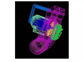
Ship Hull Form and Geometry • Since the ship is a 3-dimensional shape, data in x, y • and z directions is necessary to represent the ship hull. • Table of Offsets • Lines • - body plan (front View) • - shear plan (side view) • - half breadth plan (top view)
Half – Breadth Plan • Intersection of planes (waterlines) parallel to the baseline (keel).
Shear Plan • Intersection of planes (buttock lines) parallel to the centerline plan
Body Plan • Intersection of planes to define section line.
AP FP Shear DWL LBP LOA Basic Dimensions and Hull Form Characteristics • LOA(length over all ) : overall length of the vessel • DWL(design waterline) : water line where the ship is designed to • float • FP(forward perpendicular) : imaginary vertical line where the bow • intersects the DWL • AP(aft perpendicular) : imaginary vertical line located at either • the rudder stock or intersection of the stern with DWL
Basic Dimensions and Hull Form Characteristics AP FP Shear DWL LBP LOA • LBP (length between perpendicular) : horizontal distance • from FP and AP • Amidships : the point midway between FP and AP • Shear : longitudinal curvature given to deck
Camber Beam: B Freeboard WL Depth: D Draft: T K C L View of Mid-Ship section • Depth(D): vertical distance measured from keel to deck taken at amidships and deck edge in case the ship is cambered on the deck. • Draft(T) : vertical distance from keel to the water surface • Beam(B) : transverse distance across the each section • Breadth(B) : transverse distance measured amidships
Camber Beam: B Freeboard WL Depth: D Draft: T K C L View of Mid-Ship section • Freeboard : distance from depth to draft (reserve buoyancy) • Keel(K) : locate the bottom of the ship • Camber : transverse curvature given to deck
Flare Tumblehome • Flare: outward curvature of ship’s hull surface above the waterline • Tumble Home : opposite of flare
Drawing Ship Lines Drawing Lines Plan