Download
1 / 31
310 likes | 454 Vues
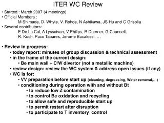
This document outlines the ongoing review of the ITER water cooling (WC) system, initiated in March 2007. It discusses the roles of official members and contributors, highlights recent group discussions, and assesses the WC system design's compatibility with operational needs for tritium management and low-Z contamination control. Key focuses include Be wall and C/W divertor design, conditioning methods during operation, dust removal strategies, and diagnostic requirements. Aiming for effective gas injection and discharge conditioning while minimizing maintenance risks, this review helps ensure safe, reproducible tokamak startup and operation.

E N D
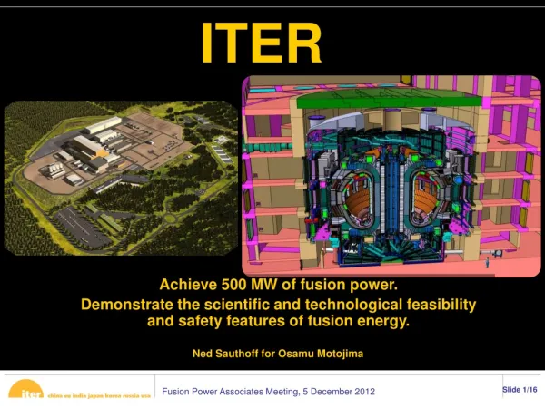
ITER WC Review • Started : March 2007 (4 meetings) • Official Members : • M Shimada, D. Whyte, V. Rohde, N Ashikawa, JS Hu and C Grisolia • Several contributors: • E De La Cal, A Lyssoivan, V Philips, R Doerner, G Counsell, • R. Koch, Paco Tabares, Jerome Bucalossi, … • Review in progress: • today report: minutes of group discussion & technical assessment • in the frame of the current design: • Be main wall + C/W divertor (not a metallic machine) • review design: review the WC system & address open issues (if any) • WC is for: • VV preparation before start up (cleaning, degreasing, Water removal,…) • conditioning during operation with and without Bt • to reduce low Z contamination • to control Be oxidation and recycling • to allow safe and reproducible start up • to permit restart after disruption • to participate to T inventory control
Oxygen in Tokamak ITER WC Control of T WC diagnostics coatings BT0 BT=0 Consequences on PFC RF Repetitive Plasma Breakdown Plasma GDC VV & PFC Preparation
GDC Surfaces Accessibility (insert & remote area) GDC GDC Operational parameters Dust removal GD BeO De-oxidation GDC Design Evolution GDC with O2 Conclusions See use of O2 In tokamak
Ferritic insert Non activated Ferritic insert (>10gauss on PFC) Ferritic insert (<10Gauss on PFC) GDC surfaces accessibility Divertor Main Vessel Remote surfaces Main Vessel ok LFS Nok HFS ok Ok If insert Non active in Div. castellations Divertor ok WC with High Energy neutral Needed ? Remote Surfaces Br to zero ( BT<0) ICRH ok castellations WC with High Energy neutral Technically possible? ICRH ok Under and in the divertor ICRH ok GC nok? Never 0? ok Oxygen Possible? WC with High Energy neutral What WC Needed ? Added anodes (heated)?
T as high as possible. Mandatory = homogeneity Use of gas (In pipe or In vessel) Not need of Be Alloy at 500°C Diagnostic in the Anode? 240°C ok If homogeneous GD Operational parameters Be on Cu? T of Surface During Glow? Coating Of electrode Wall T° Breaking voltage Too low: To 5kV (ok) T°: Calculation during Plasma operation Position of movable anode Calculation needed Insulation (Al2O3) VV pumping Speed (cryo + coal) (to be discussed) Number of Electrodes & power Too close to divertor wall Too low compare to current machines (same as AUG) Need protection from H (ok) 6 anodes 10kW each Without B, roots ok?
GD Design Evolution GD anodes on VV wall GD in remote area
Needed to prepare startup GD BeO de-oxidation Non Normal Tokamak operation: after O2 + 400°C surface T° treatment Thick oxide layer? Normal Tokamak operation oxide layer ( 5 nm) GDC Ar+ or He+ To be studied if O2 Relevant fro Tokamak treatment Rapid layer Removal? Argon trapping? Dust production? 1 days of glow Possible Not observed in Cmod 1kg of Be or BeO In 150days of glow (negligible compare to plasma) R&D needed!
Possibility to use a Anode electrode for dust recovery • Action range = several meters GD & Dust removal
Title: Divertor gas injector and subdivertor anodes for tritium/carbon co-deposition control and removal Issue Description: Redesign of the cassettes and divertor fuelling systems to allow for toroidally symmetric gas injection and local glow discharge conditioning under the dome area. Check the possibility of using the gas tubes as anodes. Heated filament (end of tube) Without Heater With Heater He, 1Pa/1A • Glow plasma not in remote zone • lack of secondary electrons • Heaters in tube: glow pushed in • Anode in tube: Glow pushed out • but : • Glow in ITER Ducts allowed? GDC in remote area
Tore Supra • Much better solution than movable anode (common advice from WC sub group) • used in several large machines (Textor/JET/AUG/Tore Supra/DIIID) • No problem of homogeneity of glow even if placed close to the wall • Pro: • No movement: minimise the risk of leak • Place for other system • Design as a small remote limiter • No pb of wall erosion • Cons: • Maintenance problem • Design: • Insulation (neutrons?) • protected cables GD: Electrodes attached to the main vessel wall W7X
GD Conclusions • GDC design simple modifications: Breakdown voltage, coatings, … • GDC and ferritic inserts: • could work if Br less than 10 Gauss • if not, procedure needed to reduce Br or other Conditioning technique (RF?) • VV pumping facility too small (to be improved?) • GDC for BeO de oxidation: ok • GDC under divertor: not ok. • design improvement possible (secondary electrons emitters?) • GDC major modification: fixed electrodes (To be studied) • GDC system use for Dust recovery (To be studied) R&D needed!
Anode Diagnostics + WC hardware system Diag: • Anode current and voltage monitor • Thermocouple in Anode • Arc detection (and limitation) • If ICRH heating antenna used (?): • embarked diag for arc detection • spectro for plasma detection • Global Diagnostics: • Very robust diagnostics needed as RGA, P gauges • but good hardware needed (good conductance) • P gauges : baratron type • Video mandatory (perhaps only H2 learning phase) • Local diagnostics needed in order to assess the homogeneity of treatment: • LIBS • Current collectors (wall langmuir probes?) • Possibility of sample collection (Hydrogen phase) WC Diagnostics
PFC surface morphology • increase of dislocation (He GDC, metal, LHD, Miyamoto, 2004) • trapped He bubbles (HeGD, metal, LHD) • gas trapping in “carbon” (?) machine (HeGD, Tore Supra) • erosion of copper mirror (HeGD, Tore Supra) • Surface composition changes • presence of metal (Fe, Cr) redeposition (He GDC, metal, LHD) • presence of metal (Fe, Cu, Ni) redeposition (He GDC, CFC, Tore Supra) • presence of carbon layers (in vessel surfaces, HeGD, TS) • Dust creation: • not yet addressed • Need of a common R&D Consequences on PFC
VV and PFC Preparation • Needs: • Procedure to prepare and installed PFC • including leak test procedures • information from all current machines needed (nothing published) • Procedure for maintenance • example of considered problems with air ingress: • Be pollution • Flaking of layers: dust production (limited inventory) • VV: • Temperature of the PFC: • as higher as possible: 240°C ok, homogeneity needed. • However, for VV preparation, Hot N2 in empty water loop could be considered • after water leak or for VV preparation. • need to be confirmed (due to mass of components) • However, Hot N2 injection in VV in order to heat PFC surfaces • Same possibility with localised heating system via laser and RH.
Repetitive plasma breakdown Why? ? How? Results Conclusions
Repetitive plasma breakdown: Why? • After disruption, (often) ramp up impossible • In TS, • Glow inefficient due to permanent Toroidal field • glow possible but lost of operational time • 30’/30’ to decrease/increase Bt • (ICRH possible but not desirable due to a leak • observed after a metallisation of the insulated feed through ) • Often, ramp up after several plasma breakdown • time consuming again • (since normal procedure of plasma start up) • In 1998, special procedure developed to realised consecutive • high frequency plasma start up and restore Ip ramp up
Repetitive plasma breakdown: How? • Repetitive alternative plasma (He), poloidal breakdown • Pulsed tension on the central solenoid coil (5 Hz square voltage) • Low plasma current (<40kA) at 10 V loop voltage (40kW/pulse) • Cycle: [2s of plasma and 8s of pumping] during 120 s
Repetitive plasma breakdown: Results (1) • All He injected is ionised during plasma • He, HD but also CO and CO2 produced • Time constant of pressure >> vessel pumping constant: • wall desorption. • Production = low but 3xGlow production (comparable time) • (equivalent to 10 minutes of HeGD)
Repetitive plasma breakdown: Results (2) • 40kW per pulse, 2.2 MJ for 120s procedure (5 more than HeGD)
Repetitive plasma breakdown: Conclusions • 1 cycle of 120s is sufficient to restart plasma (almost always) • Then a full ohmic discharge is needed (with no gas injection) • TS conditioning relies now mostly on this procedure • to start the plasma operation: D2GD followed by HeGD • (every 15 days, due to all actively cooled device) • for Wall desaturation or Disruption recovery: Repetitive Break Down • one limitation: increase of T° in the Supra coils due to eddy currents • Today, R&D studies to estimate how this conditioning procedure • is active and improve know-how. • (Possibility to study this technique for ITER)
Why? Unique possibility to condition the machine in presence of Bt (constant field) RF ITER ICRH Parameters ECRH vs ICRH Dedicated antenna or not Conclusions
RF: ECRH versus ICRH • Comparison in several machines: efficiency higher for ICRH than ECRH • Confirmed by a dedicated study in one machine: TEXTOR • ICRH “better” due to high energy ions and neutrals • Homogeneity of conditioning better with IRCH than ECRH • even if some poloidal inhomogeneities exist with ICRH • (could be optimised by low vertical field) • However, ECRH localised (BT=cst + poloidal field). good point : treat fixed location • Presence of high energy neutrals during ICRH to treat castellation • This has to be confirmed (experiment considered in TEXTOR) • ICRH does not clean shadowed areas. • However, reactive etching could be used to treat remote area (with oxygen) • (done in TEXTOR and HT-7 but ITER?)
RF: Dedicated antenna or not • Dedicated antenna needs a new design • could be studied and installed on the GDC anode (budget??) • Better solution is to use the ICRH “heating” system for conditioning: • done in almost all the machine (AUG, TEXTOR, HT-7) • (except in TS where a metallisation of insulation was observed TBC!) • minimise the risk has to be done: • R&D in the WP of current machine in order to establish right “recipe” • Optimization of gas breakdown phase • how to eliminate gas breakdown inside the antenna box? • Improvement of antenna-plasma coupling during RF plasma production • Recipes for the RF plasma homogeneity improvement in large-size machines • Control over the generation of high-energy ions/CX neutrals in ICRF plasmas. • Add diagnostics in the antenna and in weak zone to control arcing etc…
RF: ICRH Parameters for ITER • Breakdown pressure: 0.5 Pa (JET, TEXTOR, AUG) • ECRH could help to get lower BP (but need to be tested) • Low operating pressure: <0.1 Pa (to avoid arcing in antenna) • lower pressure + Higher ICRH power: higher energy per particle • (T removal considered) • P injected between 1 and 3 MW (preliminary estimation, to be confirm) • Operating with active gases possible and tested in several machines • 30 to 60 MHZ with a capability of frequency sweeping (1-3 MHz/s) • to scan the divertor area • Can be used to treat high Z material & castellations.
RF: Conclusions • ICRH more efficient than ECRH • ICRH could be used to treat castellation (to be studied) • Dedicated antenna: need of a new design (and budget!) • ICRH heating system could be used for WC (to be discussed with the Heating WG) • as in all machine • need of antenna diagnostics and protection • need R&D to establish ITER recipe
PlasmaConditioning Use plasma For conditioning Disruption cleaning Plasma Discharges
Plasma conditioning: Disruption cleaning • Possible at low Ip ITER current • Play with radiation to heat films • (massive gas injection) • High fuel desorption capability • BUT: • Homogeneity? (divertor treatment?) • Dust formation!!! • Gas trapping in the wall (pollution!) • Pb of cryo pumps capability • R&D needed (in the frame of the ITPA?)
Plasma conditioning: plasma discharges (Maingi, NF, 1996) • Proposed to remove the trapped fuel. • But (Th Loarer): • Not confirmed by T JET experiments • Play with “active surface trapping” only • (dynamic retention) • Efficient to help the start up (create a pumping wall) • Un-efficient to remove “all” the fuel trapped
(T Haasz) Oxygen in tokamak • Pro : • work with pure C films • acts in remote places (!) • Cons: • not working with mixture • oxide protection • much more high T° to remove carbon if Be inclusions • not working at low T° • Could be induced locally by laser: more complicated • pb of flaking • to high T concentration in water (not possible to process) 623K 523K • Conclusions: • Even if not in the scope of this review, O2 not relevant (?) for ITER detritiation. • Forum needed: • to coordinate a “systemic” approach • to propose a coordinate WP • to determine the better gas to be used
Coatings • Coatings not needed in a Be machine. • not the case for an all metal machine! • Question : is div. transient coating needed for X point preparation? • If coating needed: • Be evaporator not suitable (?) (Magnetic field, place, line of sight) • Diborane injection in GD good solution. • (possibility of Diborane injection in current ramp down?). • Need of • Local gas injector in the divertor region • Dedicated pumping system (cryo pollution if )
Design of movable electrode • The GDC design has been modified. • Due to the weight of the electrode (250kg), the articulation is removed • In that case, the GDC anode goes in the VV almost horizontally. • The electrode is 150mm in diameter. X