Isoparametric elements
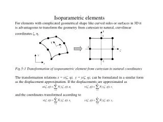
Isoparametric elements For elements with complicated geometrical shape like curved sides or surfaces in 3D it is advantageous to transform the geometry from cartesian to natural, curvilinear coordinates ζ, η. Fig.5-1 Transformation of isoparametric element from cartesian to natural coordinates

Isoparametric elements
E N D
Presentation Transcript
Isoparametric elements For elements with complicated geometrical shape like curved sides or surfaces in 3D it is advantageous to transform the geometry from cartesian to natural, curvilinear coordinates ζ, η. Fig.5-1 Transformation of isoparametric element from cartesian to natural coordinates The transformation relations x = x(ζ, η), y = y(ζ, η), can be formulated in a similar form as the displacement approximation. If the displacements are approximated as and the coordinates transformed according to
Then, in case of the element is called isoparametric. The reason is that we need the same number of deformation parameters ui, vi to describe displacement field as the number of nodal coordinates xi, yi to describe element geometry. Shape functions of isoparametric elements can be described in a systematic way as families of certain type and we shall mention two of such types - families with linear and quadratic shape functions. ISOPARAMETRIC ELEMENTS WITH LINEAR SHAPE FUNCTIONS 1D elements Linear shape functions expressed in natural coordinate over a unit element Nζ1 = ( 1 – ζ ) / 2 , Nζ2 = ( 1 + ζ ) / 2 are plotted in Fig.5-2 Fig.5-2 Linear shape functions
We note that they are the shape functions of LINK1 and LINK8 elements, described previously. 2D elements - bilinear element Fig.5-3 Bilinear element in cartesian and natural coordinates Bilinear element in Fig.5-3 has shape functions generated by multiplying linear expressions in ζ and η direction. Due to multiplication, the product is not a linear function: N1 = Nζ1 . Nη1 = (1 - ζ).(1 - η ) / 4 N2 = Nζ2 . Nη1 = (1 + ζ).(1 - η ) / 4 N3 = Nζ2 . Nη2 = (1 + ζ).(1 + η ) / 4 N4 = Nζ1 . Nη2 = (1 - ζ).(1 + η ) / 4
One of the shape functions is shown in Fig.5-4a). Besides the basic isoparametric functions, quadratic „extra“ shape functions are sometimes used to improve the quality of bilinear element. Fig.5-4 Isoparametric a) and extra b), c) shape functions of bilinear element In ANSYS, this quadrilateral element can be found under the names PLANE42, or PLANE182. As mentioned, triangular form of this element can be used, too. Examples 5.1 and 5.2 show improved quality of the bilinear element with extra shapes in comparison to a standard bilinear, and especially to triangular element.
3D elements with linear functions in ζ, η and ξ Eight shape functions of the hexaedral element according to Fig.5-6 a) are created by mutual multiplication of linear functions in ζ, η and ξ : They are often complemented by extra quadratic shape functions, improving the element properties :
Besides the hexaedral shape, other „degenerated“ element shapes ACCORDING TO Fig5-6 b),c),d) can be obtained. In some FE systems such elements are classified as special types, in ANSYS they are all seen as degenerated shapes of the same element SOLID45 or SOLID 185. Fig.5-6 Eight node hexaedral element and its degenerated shapes The shape 5-6 a) is used to create mapped meshes, which are saving computer time and memory, but are difficult to prepare. The shape 5-6 d) is used for fully automatic free meshing, and the intermediate shapes b), c) can be used for transition between these two mesh types.
ISOPARAMETRIC ELEMENTS WITH QUADRATIC SHAPE FUNCTIONS 1D elements Quadratic shape functions expressed in natural coordinate over an unit element are plotted in Fig.5-7 Fig.5-7 Quadratic 1D element and its shape functions
2D quadratic elements By a systematic evolution of quadratic elements, similar to the evolution of linear elements we obtain 9-node plane element according to Fig.5-8 a). Its nine shape functions are obtained by multiplication of qudratic functions from the preceding paragraph: N1 = 2Nζ1 .2Nη1, N2 = 2Nζ2 .2Nη1, N3 = 2Nζ3 .2Nη1, N4 = 2Nζ3 .2Nη2, N5 = 2Nζ3 .2Nη3, N6 = 2Nζ2 .2Nη3, N7 = 2Nζ1 .2Nη3, N8 = 2Nζ1 .2Nη2, N9 = 2Nζ2 .2Nη2, Practical usage of this element is limited and the 8-node version according to Fig.5-8 b) prevails. In ANSYS, degenerated triangular form with curved sides (Fig. 5-8 c) is included in the same element type PLANE82, or PLANE183. Fig.5-8 2D quadratic elements
3D quadratic elements In a 3D space, internal face and body nodes are always excluded and the hexaedral form of element has then 20 nodes with 60 degrees of freedom (Fig.5-9a). In ANSYS this element can be found under the name SOLID95, or SOLID186 and also its other geometrical forms (Figs.5-9b,c,d) belong to the same element type. Like the linear 3D elements, the shape 5-9 a) is used for mapped meshes, 5-6 d) for fully automatic free meshing, and the intermediate shapes b), c) can be used for transition between these two mesh types. Fig.5-9 Twenty-node hexaedral element and its degenerated shapes
Discussion of element quality The question which element to use is always open and will be hardly ever finally answered. It always depends on circumstances and only general advice can be given. For regular shapes, mapped hexaedral mesh always leads to more effective computational models, but its preparation may be an exhausting man-controlled task. Fully automatic free meshing by tetraedral elements can be used for easy model preparation even for complicated shapes, such models then need more computational power to solve. Quadratic 10-node tetraedral elements should be preferred in such cases over linear 4-node tetraedra. Some insight into the behaviour and quality of 3D elements gives the Example 5.3.