Download
1 / 44
761 likes | 1.58k Vues
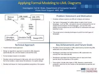
Chapter 28 UML Activity Diagrams and Modeling. “ If it wasn’t backed-up, then it wasn’t important . ” - The Sysadmin Motto. Objectives Introduce UML activity diagram notation, with examples, and various modeling applications. Introduction.

E N D
Chapter 28UML Activity Diagrams and Modeling “ If it wasn’t backed-up, then it wasn’t important.” - The Sysadmin Motto Objectives • Introduce UML activity diagram notation, with examples, and various modeling applications. CS319 Week 11 - Nov.21,2005
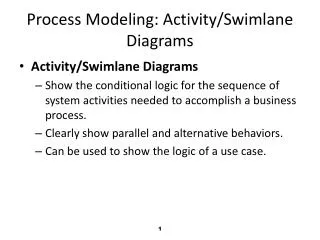
Introduction • A UML activity diagram shows sequential and parallel activities in a process. • They are useful for modeling business processes, workflows, data flows, and complex algorithms as well as use cases. CS319 Week 11 - Nov.21,2005
Fig 28.1 Basic UML activity diagram notation. Once an action is finished, there is an automatic outgoing transition. The diagram can show both control flow and data flow. CS319 Week 11 - Nov.21,2005
Business Process Modeling • “A picture worth a thousand words.” • Use activity diagrams when necessary to understand complex business processes by visualizing them. • See multiple parties and parallel actions involved at once. Fig 28.2 Classic DFD notation. CS319 Week 11 - Nov.21,2005
Data Flow Modeling • In the 1970s, Data Flow Diagrams (DFD) became a popular way to visualize the major steps and data involved in softwarea system processes. • DFDs were useful to document the major data flows or to explore a new high-level design in terms of data flow. • UML activity diagrams can be used for data flow modeling, replacing traditional DFD notation. CS319 Week 11 - Nov.21,2005
Fig. 28.3 Applying activity diagram notation to show a data flow model. CS319 Week 11 - Nov.21,2005
Fig. 28.4 An activity will be expanded in another diagram. CS319 Week 11 - Nov.21,2005
Fig. 28.5 The expansion of an activity. CS319 Week 11 - Nov.21,2005
Fig. 28.6 Signals. CS319 Week 11 - Nov.21,2005
Guidelines • Activity modeling proves most valuable for complex processes, usually involving many parties. Use-case text suffices for simple processes. • If modeling a business process, take advantage of the “rake” notation and sub-activity diagrams. • On the first overview “level 0” diagram, keep all the actions at a very high level of abstraction, so that the diagram is short and sweet. • Expand the detains in subdiagrams at “level 1” and so on. CS319 Week 11 - Nov.21,2005
Fig. 28.7 Modeling the Process Sale use case with an activity diagram. CS319 Week 11 - Nov.21,2005
Process: Activity Diagrams in the UP • One of the UP disciplines is Business Modeling; its purpose is to understand and communicate “the structure and dynamics of the organization in which a system is deployed.” • A key artifact of the Business Modeling discipline is the Business Object Model, a superset of the UP Domain Model • visualizes how a business works, using UML class, sequence, and activity diagrams. CS319 Week 11 - Nov.21,2005
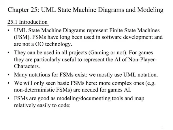
Chapter 29UML State Machine Diagrams and Modeling “ No, no you’re not thinking, you are just being logical.” - Niels Bohr Objectives • Introduce UML state machine diagram notation, with examples, and various modeling applications. CS319 Week 11 - Nov.21,2005
Introduction • As with activity diagrams, UML sate diagrams show a dynamic view. • İllustrates the events and states of things – transactions, use cases, people, and so forth. CS319 Week 11 - Nov.21,2005
Fig. 29.1 State machine diagram for a telephone. • Illustrates the interesting events and states of an object, and the behavior of an object in reaction to an event. • A state machine diagram shows the lifecycle of an object: what events it experiences, its transitions, and the states it is in between these events. CS319 Week 11 - Nov.21,2005
Events, States and Transactions • Event – is an occurrence that triggered the state. • A telephone receiver is taken off the hook. • State – is the condition of a object at a specific time. • A telephone is on “idle” state until it is taken from the hook. • Transition – involves going from one state to the other when an event occurs. Transitions are label in form: Event [Guard] / Action. • When the event “off hook” occurs, transition the telephone from the “idle” state to the “active” state. CS319 Week 11 - Nov.21,2005
Types of Events • External Event – Events caused by an outside actor, outside of the system’s boundary. • Internal Event – Events caused by an internal action, inside the system’s boundary. • Temporal Event – Events caused by a determined date or time clock. CS319 Week 11 - Nov.21,2005
State-Independent and State-Dependent Objects • If an object always responds the same way to an event, then it is considered state-independent (or modeless) wrt that event. • By contrast, state-dependent objects react differently to events depending on their state or mode. • Guideline: Consider state machines for state-dependent objects with complex behavior, not for state-independent objects. CS319 Week 11 - Nov.21,2005
Modeling State-Dependent Objects • Physical Devices controlled by Software • Microwave oven, Radio • Transactions - The way transaction respond to events • Cancel a sale • Role Mutators, i.e., Objects that change their role. • Full-time vs. half-time worker • Communication Protocols • UI Page/Window Flow or Navigation • UI Flow Controllers or Stateful Sessions • Server-side software objects • Use Case System Operations • For Process Sale: makeNewSale, enterItem, etc. • Indivitual UI Window Event Handling • Window’s action “Edit-Copy” CS319 Week 11 - Nov.21,2005
Fig. 29.2 Transaction action and guard notation. CS319 Week 11 - Nov.21,2005
Fig. 29.3 Nested states. CS319 Week 11 - Nov.21,2005
Fig. 29.4 Applying a state machine to Web page navigation modeling. CS319 Week 11 - Nov.21,2005
Fig. 29.5 A sample state machine for legal sequence of use case operations. CS319 Week 11 - Nov.21,2005
Process: State Machine Diagrams in the UP • There is not one model in the UP called the “state model.” • Any element in any model (Design Model, Domain Model, Business Object Model, etc.) may have a state machine to better understand or communicate its dynamic behavior in response to events. CS319 Week 11 - Nov.21,2005
Chapter 30Relating Use Cases “ Why do programmers get Halloween and Christmass mixed up? Because OCT(31) = DEC(25).” Objectives • Relate use cases with include and extend associations, in both text and diagram formats. CS319 Week 11 - Nov.21,2005
Introduction • Use cases can be related to each other. For example, a subfunction use case such as Handle Credit Payment may be part of several use cases, such as Process Sale or Process Rental. • Organizing use cases into relationships has no impact on the bahavior or requirements of the system. • Rather, it is simply an organization machanigm to (ideally) improve communication and comprehension of the use cases, reduce duplication of text, and improve management of the use case documents. CS319 Week 11 - Nov.21,2005
Guideline • Avoid agonizing over use case relationships • Do not spend unproductive time on debating how to relate use cases in a use case diagram, rather do the important work: writing text. CS319 Week 11 - Nov.21,2005
The include Relationship • This is the most common and important relationship. • It is common to have some partial behavior that is common across several use cases. Rather than duplicate this text, it is desirable to separate it into its own subfunction use case, and indicate its inclusion. • Guideline: Use include when you are repeating yourself in two or more separate use cases and you want to avoid repetition. • Guideline: Decompose an overwhelmingly long use case into subunits to improve comprehension. CS319 Week 11 - Nov.21,2005
Using include with Asynchronous Event Handling • Use include to describe the handling of an asynchronous event, such as when a user is able to, at any time, select or branch to a particular window, function, or Web page, or within a range of steps. CS319 Week 11 - Nov.21,2005
Concrete, Abstract, Base and Addition Use Cases • A concrete use case is initiated by an actor and performs the entire behavior desired by the actor. There are the elementary business process use cases. • Ex. Process Sale • An abstract use case is never instantiated by itself; it is a subfunction use case that is part of another use case. • Ex. Handle Credit Payment • A use case that includes another use case, or that is extended or specialized byanother use case is called a base use ease. • Ex. Process Sale wrt Handle Credit Payment • The use case that is an inclusion, extension, or specialization is called an addition use case. • Ex. Handle Credit Payment in the include relationship to Process Sale. • Addition use cases are usually abstract. Base use cases are usually concrete. CS319 Week 11 - Nov.21,2005
The extend Relationship • Suppose a use case’s text should not be modified for some reason, perhaps it is baselined as a stable artifact, and can’t be touched. • How to append to theuse case without modifying its original text? • The extend relationship provides an answer. The idea is to create an extending or addition use case, and within it, describe where and under what condition it extends the behavior of some base use case. • Some use case guidelines recommend using extending use cases and the extend relationships to model conditional or optional behavior inserted into the base use case. • Guideline: Prefer to use the Extensions section when possible to avoid further complication. CS319 Week 11 - Nov.21,2005
2. Cashier enters gift certificate ID. CS319 Week 11 - Nov.21,2005
Fig. 30.1 Use case include relationship in the Use-Case Model. CS319 Week 11 - Nov.21,2005
Fig. 30.2 The extend relationship. CS319 Week 11 - Nov.21,2005
Chapter 20Mapping Designs to Code “ Beware of bugs in the above code; I have only proved it correct, not tried it.” - Donald Knuth Objectives • Map design artifacts to code in an object-oriented language. CS319 Week 11 - Nov.21,2005
Introduction • With the completion of interaction diagrams and DCDs for the current iteration of the case studies, there is more than enough thought and detail to cut some code for the domain layer of objects. • The UML artifacts created during design work will be used as inpıt to the code generation process. • UP Implementation Model is all the implementation artifacts, such as source code, database definitions, JSP/XML/HTML pages, and so forth. • Implementation in an O-O Language requires writing source code fo • Class and interface definitions • Method definitions. CS319 Week 11 - Nov.21,2005
Defining a Class with Method Signatures and Attributes Fig. 20.1 SalesLineItem in Java. CS319 Week 11 - Nov.21,2005
Creating Methods from Interaction Diagrams Fig. 20.2 The enterItem interaction diagram. CS319 Week 11 - Nov.21,2005
Fig. 20.3 The Register class. CS319 Week 11 - Nov.21,2005
Fig. 20.4 The enterItem method. CS319 Week 11 - Nov.21,2005
Collection Classes in Code Fig. 20.5 Adding a collection. CS319 Week 11 - Nov.21,2005
Fig. 20.6 Sale.makeLineItem method. CS319 Week 11 - Nov.21,2005
Order of Implementation Fig. 20.7 Possible order of class implementation and testing. CS319 Week 11 - Nov.21,2005