
68000 Arithmetic Instructions
E N D
Presentation Transcript
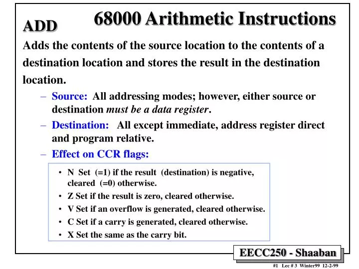
68000 Arithmetic Instructions ADD Adds the contents of the source location to the contents of a destination location and stores the result in the destination location. • Source: All addressing modes; however, either source or destination must be a data register. • Destination: All except immediate, address register direct and program relative. • Effect on CCR flags: • N Set (=1) if the result (destination) is negative, cleared (=0) otherwise. • Z Set if the result is zero, cleared otherwise. • V Set if an overflow is generated, cleared otherwise. • C Set if a carry is generated, cleared otherwise. • X Set the same as the carry bit.
68000 Arithmetic Instructions ADDQ Adds an immediate literal in the range 1 to 8 to an address location or a register location. • Source: An immediate value in the range 1 to 8 • Destination: All except immediate, and program relative. • Effect on CCR flags: • N Set (=1) if the result (destination) is negative, cleared (=0) otherwise. • Z Set if the result is zero, cleared otherwise. • V Set if an overflow is generated, cleared otherwise. • C Set if a carry is generated, cleared otherwise. • X Set the same as the carry bit. Condition codes not affected when the destination is an address register.
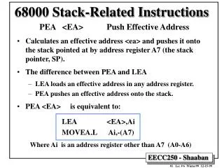
Example: Counting 6’s in An Array • A region of memory starting at location $1000 contains an array of 20 one-byte values. • This program counts the number of 6’s in this array and stores the count in register D1. ORG $400 Program origin LEA Array,A0 A0 points to the start of the array MOVE.B #20,D0 20 values to examine CLR.B D1 Clear the 6’s counter Next MOVE.B (A0)+,D2 Pick up an element from the array CMPI.B #6,D2 Is it a 6? BNE Not_6 IF not 6 THEN skip counter increment ADDQ.B #1,D1 IF 6 THEN bump up 6’s counter Not_6 SUBQ.B #1,D0 Decrement loop counter BNE Next Repeat 20 times STOP #$2700 Halt processor at end of program ORG $1000 Array DC.B 1,6,4,5,5,6,2,5,6,7,6,6,6,1,3,5,9,6,7,5 END $400
68000 Arithmetic Instructions ADDI Add immediate: Adds an immediate value to a destination operand and stores the results in the destination. This can be used to add an immediate value to a memory location. • Source: Immediate value. • Destination: All except address register direct, program counter relative and immediate. • Effect on CCR flags: • N Set (=1) if the result (destination) is negative, cleared (=0) otherwise. • Z Set if the result is zero, cleared otherwise. • V Set if an overflow is generated, cleared otherwise. • C Set if a carry is generated, cleared otherwise. • X Set the same as the carry bit.
68000 Arithmetic Instructions ADDX Adds the contents of the source location and the X flag to the contents of a destination location and stores the result in the destination location. • Source: All addressing modes; however, either source or destination must be a data register. • Destination: All except immediate, address register direct and program relative. • Effect on CCR flags: • N Set (=1) if the result (destination) is negative, cleared (=0) otherwise. • Z Set if the result is zero, cleared otherwise. • V Set if an overflow is generated, cleared otherwise. • C Set if a carry is generated, cleared otherwise. • X Set the same as the carry bit. The instructions SUB, SUBA, SUBQ, SUBI and SUBX are the subtraction equivalent of the corresponding ADD instructions.
Sign EXTend Instruction EXT Extends the sign bit of the low-order byte or word of a data register: • EXT.W sign extends the low order byte to 16 bits; • EXT.L sign extends the low order word to 32 bits. • Example: D0 = $000000C3 Before EXT.W D0 D0= $0000FFC3 After sign extend D1 = $0000E1FC Before EXT.L D1 D0= $FFFFE1FC After sign extend
68000 Arithmetic Instructions MULS, MULU <ea>,Dn MULU performs unsigned multiplication and MULS performs signed multiplication on two's complement numbers. • Multiplication is a 16-bit operation that multiplies the low-order 16-bit word in Dn (destination data register) by the 16-bit word at the effective address. The 32-bit results is stored in the full destination data register Dn. • Source: All modes except address register direct. • Destination: Data register. • Effect on CCR flags: • N Set if the result is negative, cleared otherwise. • Z Set if the result is zero, cleared otherwise. • V Set if an overflow, cleared otherwise. • C Always cleared. • X Not affected.
Multiply signed: Multiply unsigned: D0 D0 Before Before 31 31 31 31 16 16 16 16 15 15 15 15 0 0 0 0 1 0 1 0 1 0 1 0 1 0 1 0 1 0 1 0 Don’t care Don’t care 0 0 0 0 0 0 0 0 0 0 1 0 1 0 1 0 1 0 1 0 1 0 1 0 1 0 0 0 0 0 0 0 1 0 1 0 1 0 1 0 1 0 0 0 0 0 0 0 1 1 1 1 1 1 1 1 1 1 1 0 1 0 1 0 1 0 1 0 1 0 1 0 1 0 1 0 1 0 1 0 MULU #%01000000,D0 or MULU #$40,D0 MULS #%01000000,D0 or MULS #$40,D0 D0 D0 After After Sign extension MULU, MULS Example
68000 Arithmetic Instructions DIVS, DIVU DIVU performs unsigned division, and DIVS performs signed division on two's complement numbers. • The 32-bit long word in the data register is divided by the 16-bit word at the effective address. • The 16-bit quotient is stored in the lower-order word of the register and the remainder is stored in the upper-order word. • Source: All modes except address register direct. • Destination: Data register. • Effect on CCR flags: • N Set if the quotient is negative, cleared otherwise. Undefined if overflow or divide by zero occurs. • Z Set if quotient is zero, cleared otherwise. Undefined if overflow or divide by zero occurs. • V Set if division overflow occurs, cleared otherwise. Undefined if overflow or divide by zero occurs. • C Always cleared. • X Not affected.
Divide signed: Divide unsigned: D0 D0 Before Before 31 31 31 31 16 16 16 16 15 15 15 15 0 0 0 0 1 1 1 1 1 1 1 1 1 1 1 1 0 1 1 0 1 1 1 1 1 0 1 0 0 0 0 0 0 0 0 0 1 1 1 1 1 1 1 1 1 1 1 1 0 1 1 1 0 0 0 0 0 0 0 0 0 0 0 0 1 0 0 1 0 0 0 0 0 1 1 0 0 0 0 0 0 0 0 0 0 0 0 0 0 0 0 0 0 0 0 0 0 0 0 1 1 0 0 0 0 0 0 0 0 0 0 0 1 0 0 1 0 1 1 1 1 1 1 1 1 1 1 1 0 1 1 1 DIVU #%01000000,D0 or DIVU #$40,D0 DIVS #%01000000,D0 or DIVS #$40,D0 D0 D0 After After DIVU, DIVS Example D0 = 98309 divide by 64 Remainder = 5 Quotient = 1536 D0 = - 98309 divide by 64 Remainder = -5 Quotient = - 1536
Example: Adding Elements of An Array • A region of memory starting at location $1000 contains an array of 10 one-byte signed values (i.e. In 2’s complement representation) • This program adds the elements of this array and stores the sum in register D2 as a long word. ORG $400 Program origin LEA Array,A0 A0 points to the start of the array MOVE.B #10,D0 10 values to add CLR.B D1 Clear temporary register D1 CLR.L D2 Clear the sum register Next MOVE.B (A0)+,D1 Copy an element from the array in D1 EXT.W D1 Extend element sign to word size EXT.L D1 Extend element sign to long word ADD.L D1,D2 Add array element to the sum in D2 SUB.B #1,D0 Decrement loop counter BNE Next Repeat 10 times STOP #$2700 Halt processor at end of program ORG $1000 Array DC.B $EF,$CD,$CC,$0A,$FF,$DA,$91,$DD,$4A,$8D END $400
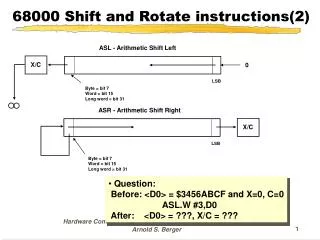
Arithmetic Shift Left Instruction The arithmetic shift left operation ASL moves the bits of the operand the specified immediate number of positions in the range 1 to 8 to the left; or by the value in a source data register modulo 64 e.g., ASL.B #3,D0 • Shifts the low byte of the D0 register 3 positions to the left. • This has the effect of multiplying by 2-cubed or 8. • As each bit is shifted left, it is stored in the Carry flag of the CCR. • The vacant spot on the right is filled with a zero. • For example: [D0.B] = 00010111 Before ASL.B #3,D0 [D0.B] = 10111000 After
Arithmetic Shift Right Instruction The arithmetic shift right operation ASR moves the bits of the operand the specified immediate number of positions in the range 1 to 8 to the right; or by the value in a source data register modulo 64 e.g., ASR.B #3, D0 • Shifts the low byte of the D0 register 3 positions to the right. • This has the effect of dividing by 2 for each position shifted. • For example: [ D0.B] = 00010111 Before ASR.B #3, D0 [D0.B] = 00000010 After • The bit shifted off the right side is stored in the Carry flag of the CCR. • On the left side, the MSB is propagated to the left (also called sign extension). For example: [D0.B] = 11101001 Before ASR.B #3,D0 [D0.B] = 11111101 After
Arithmetic Shift InstructionsOperation of ASL, ASR Operand Size: Byte, Word Long Word
Effect of Arithmetic Operations on the CCR: Example ADD.B SUB.B CLR.B ASL.B ASR.B Source 01101011 (107) 01101011 (107) 01101011 (107) 01101011 (107) 01101011 (107) Destination 01011010 (90) 01011010 (90) ( before) Destination 11000101 11101111 00000000 11010110 00110101 (after) CCR 0 1 0 1 0 0 1 0 0 0 - 0 1 0 0 0 1 0 1 0 1 0 0 0 1 XNZVC XNZVC XNZVC XNZVC XNZVC
68000 Logic Instructions Logic instructions include: AND Bit-wise AND ANDI Bit-wise AND with Immediate source OR Bit-wise OR ORI Bit-wise OR with Immediate source EOR Bit-wise Exclusive OR EORI Exclusive OR with Immediate source NOT 1’s Complement of bits of destination Effect on CCR: • X Not affected. • N Set if the most significant bit of the result is set; cleared otherwise. • Z Set if the result is zero; cleared otherwise. • V Always cleared. • C Always cleared. Examples: AND -(A0),D1 ANDI.B #$CD,D0 ANDI #%00101,CCR NOT.L D1 OR.L (A1)+ ,D2
Logical Shift Instructions LSL / LSR Logical Shift Left/Right Shifts the operand the specified number of positions left/right; vacated bit positions are always zero-filled. • The shift count for the shifting of a register is specified in two different ways: • Immediate: : in the range 1 to 8. • Register: The shift count is the value in the data register specified in the instruction modulo 64. Effect on CCR: • X Set according to the last bit shifted out of the operand; unaffected for a shift count of zero. • N Set if the result is negative; cleared otherwise. • Z Set if the result is zero; cleared otherwise. • V Always cleared. • C Set according to the last bit shifted out of the operand; cleared for a shift count of zero.
Logical Shift InstructionsOperation of LSL, LSR Operand Size: Byte, Word Long Word
Logical Shift Instructions ROL / RORRotate Left/Right Shifts or rotate the operand the specified number of positions left/right. Bits that move off one end are put back on the opposite end after setting or clearing the C-bit. • The shift count for the shifting of a register is specified in two different ways: • Immediate: in the range 1 to 8. • Register: The shift count is the value in the data register specified in the instruction modulo 64. Effect on CCR: • X Not affected. • N Set if the most significant bit of the result is set; cleared otherwise. • Z Set if the result is zero; cleared otherwise. • V Always cleared. • C Set according to the last bit rotated out of the operand; cleared when the rotate count is zero.
Rotate Left/Right Instructions :Operation of ROL, ROR Operand Size: Byte, Word Long Word
Logical Shift Operations ROXL, ROXR Rotate Left/Right with eXtend Shifts the operand the specified number of positions left/right including the X-bit a number of positions in the range 1 to 8 to the right; or by the value in a source data register modulo 64 • Example: ROXR.B #1,D0 • moves bit 7 to 6, bit 6 to 5… bit 1 to 0, • moves bit 0 to the X-bit and the X-bit to bit 7. Effect on CCR: • X Set to the value of the last bit rotated out of the operand; unaffected when the rotate count is zero. • N Set if the most significant bit of the result is set; cleared otherwise. • Z Set if the result is zero; cleared otherwise. • V Always cleared. • C Set according to the last bit rotated out of the operand; when the rotate count is zero, set to the value of the extend bit.
Rotate Left/Right with eXtend Instructions :Operation of ROXL, ROXR Operand Size: Byte, Word Long Word
One Byte Parity Bit Example: Setting Parity Bit of A Byte • The following program sets the parity bit (msb) of a byte depending on the number of 1’s in the byte using rotate. • If number of ones is odd parity bit is set( = 1), otherwise = 0 * D0 contains the byte of data whose parity bit is to be set * D1 contains a temporary working copy of D0 * D2 used to count that 7 bits have been tested ORG $400 Program origin MOVE #7,D2 Set the counter to 7 ANDI.B #%01111111,D0 Clear the parity bit to start MOVE D0,D1 Make a working copy of D0 Next ROR.B #1,D1 Rotate 1 bit right BCC Zero If the bit is 1 then EORI.B #%10000000,D0 toggle the parity bit Zero SUB.B #1,D2 Decrement the counter BNE Next Check another bit STOP #$2700 END $400
Bit Manipulation Instructions • The 68000 four instruction that manipulate single bits: • BTST Tests the value of a bit. If zero, the Z-flag is set. • BSET Sets the specified bit to 1. • BCLR Sets the specified bit to 0. • BCHG Toggles (reverses) the specified bit. • The bit number for this operation can be specified in one of two ways: • Immediate: e.g. #0, #1, #2, ... • Register: The specified data register contains the position of the bit to be manipulated. • Operations are performed on: • 1 bit of a byte if the operand is in memory or • 1 bit of a long word if the operand is a data register. Thus: • No instruction extension is required.
One Byte Parity Bit Example: Setting Parity Bit of A Byte • The following program sets the parity bit (msb) of a byte depending on the number of 1’s in the byte. • If number of ones is odd parity bit is set( = 1), otherwise = 0 * D0 contains the byte of data whose parity bit is to be set * D1 contains a counter which will range from 6 to 0 ORG $400 Program origin MOVE #6,D1 Set the counter to 6 BCLR #7,D0 Clear the parity bit to start Next BTST D1,D0 Test the bit specified by D1 BEQ Zero If the bit is 1 then toggle parity bit BCHG #7,D0 toggle the parity bit Zero SUB.B #1,D1 Decrement the counter BCC Next Check another bit STOP #$2700 END $400