Download
1 / 1
10 likes | 110 Vues
Experimental investigation of the role of interfacial area in two-phase flow models using glass etched micro-models. N.K. Karadimitriou, S.M. Hassanizadeh and P. J. Kleingeld. Utrecht University, Earth Sciences Department, Faculty of Geosciences.

E N D
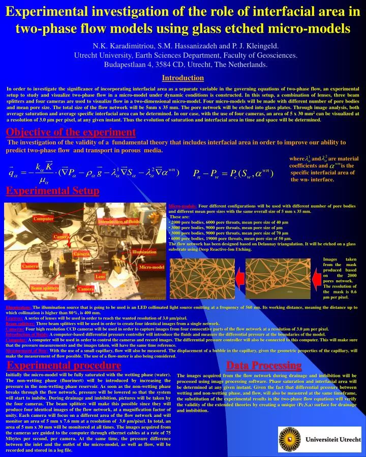
Experimental investigation of the role of interfacial area in two-phase flow models using glass etched micro-models N.K. Karadimitriou, S.M. Hassanizadeh and P. J. Kleingeld. Utrecht University, Earth Sciences Department, Faculty of Geosciences. Budapestlaan 4, 3584 CD, Utrecht, The Netherlands. Introduction In order to investigate the significance of incorporating interfacial area as a separate variable in the governing equations of two-phase flow, an experimental setup to study and visualize two-phase flow in a micro-model under dynamic conditions is constructed. In this setup, a combination of lenses, three beam splitters and four cameras are used to visualize flow in a two-dimensional micro-model. Four micro-models will be made with different number of pore bodies and mean pore size. The total size of the flow network will be 5mm x 35 mm. The pore network will be etched into glass plates. Through image analysis, both average saturation and average specific interfacial area can be determined. In our case, with the use of four cameras, an area of 5 x 30 mm2 can be visualized at a resolution of 3.0 μm per pixel, at any given instant. Thus the evolution of saturation and interfacial area in time and space will be determined. Objective of the experiment The investigation of the validity of a fundamental theory that includes interfacial area in order to improve our ability to predict two-phase flow and transport in porous media. Experimental Setup where and are material coefficients and is the specific interfacial area of the wn- interface. • Micro-models:Four different configurations will be used with different number of pore bodies and different mean pore sizes with the same overall size of 5 mm x 35 mm. • These are: • 2000 pore bodies, 6000 pore throats, mean pore size of 40 μm • 3000 pore bodies, 9000 pore throats, mean pore size of μm • 3000 pore bodies, 9000 pore throats, mean pore size of 70 μm • 6000 pore bodies, 19000 pore throats, mean pore size of 50 μm. • The flow network has been designed based on Delaunay triangulation. It will be etched on a glass substrate using Deep Reactive-Ion Etching. Computer Introduction of fluids Images taken from the mask produced based on the 2000 pores network. The resolution of the mask is 0.6 μm per pixel. Camera Illumination Camera Camera Micro-model Lens Illumination:The illumination source that is going to be used is an LED collimated light source emitting at a frequency of 560 nm. Its working distance, meaning the distance up to which collimation is higher than 80%, is 400 mm. Lens(es):A series of lenses will be used in order to reach the wanted resolution of 3.0 μm/pixel. Beam splitters:Three beam splitters will be used in order to create four identical images from a single network. Cameras:Four high resolution CCD cameras will be used in order to capture images from four consecutive parts of the flow network at a resolution of 3.0 μm per pixel. Introduction of fluids:A computer-based differential pressure controller will introduce the fluids and measure the differential pressure at the boundaries of the model. Computer:A computer will be used in order to control the cameras and record images. The differential pressure controller will also be connected to this computer. This will make sure that the pressure measurements and the images taken, will have the same time reference. Measurement of flow:With the use of a small capillary, flow will also be measured. The displacement of a bubble in the capillary, given the geometric properties of the capillary, will make the measurement of flow possible. The use of a flow-meter is also being considered. Beam splitters Camera Data Processing Experimental procedure Initially the micro-model will be fully saturated with the wetting phase (water). The non-wetting phase (fluorinert) will be introduced by increasing the pressure in the non-wetting phase reservoir. As soon as the non-wetting phase breaks through the flow network, pressure will be lowered so that the system will start to imbibe. During drainage and imbibition, pictures will be taken by the four cameras. The beam splitters will make this possible since they will produce four identical images of the flow network, at a magnification factor of unity. Each camera will focus on a different area of the flow network and will monitor an area of 5 mm x 7.6 mm at a resolution of 3.0 μm/pixel. In total, an area of 5 mm x 30 mm will be monitored at all times. The images acquired from the cameras are guided to the computer through ethernet cables at a rate of 75 Mbytes per second, per camera. At the same time, the pressure difference between the inlet and the outlet of the micro-model, as well as flow, will be recorded and stored in a log file. The images acquired from the flow network during drainage and imbibition will be processed using image processing software. Phase saturation and interfacial area will be determined at any given instant. Given the fact that differential pressure between wetting and non-wetting phase, and flow, will also be measured at the same timeframe, the substitution of the experimental results in the two-phase flow equations will verify the validity of the extended theories by creating a unique (Pc,S,a) surface for drainage and imbibition.