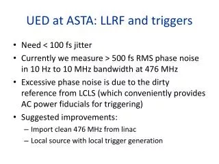
Download
1 / 9
90 likes | 218 Vues
This document outlines the commissioning plan for Ultrafast Electron Diffraction (UED) at ASTA, covering preparation, operation, and e-beam characterization phases. Key aspects include pre-operation preparations, safety protocols, equipment alignment, and training. The plan focuses on ensuring optimal overlap between laser and e-beam, both transverse and temporal, for effective machine operation starting August 1st. It details the necessary checklists, diagnostics, data acquisition processes, and machine operation parameters, ensuring the successful execution of experiments using ultrafast response samples.

E N D
Commissioning plan for UED@ASTA Renkai Li 5/20/2014 ALD UED@ASTA Review
Outline • Pre-operation preparation • Commissioning plan • Machine operation and e-beam characterization • Transverse overlap of laser and e-beam • Temporaloverlap of laser and e-beam • Summary
Pre-operation preparation • Checklist • Safety • Training • Trigger and timing • Equipment protection • Modulator, klystron, LL and high power rf • Alignment • rf gun • Laser • Magnets and power suppliers • Motors/actuators • Cameras • Diagnostics • Data management • Software UED@ASTA preparation checklist
Pump-probe control and data acquisition delay stage Computer S1 S2 > 100 M/s BS D2 D1 C2 1 1 1 EMCCD e-beam sample gun control trigger Shutter S1/S2 control To be built and tested off-line. Sample holder delay stage acquire photodiode D1/D2 transfer Virtual pump Camera C2 Computer EMCCD
Commissioning plan • Laser optics installed by July 15th • Beamline installation July 15th– July 31th • Aim to run e-beams starting from August 1stw/o sample chamber
Machine operation and e-beam characterization • Most tasks ready by August 1st • Safety • Training • Trigger and timing • Equipment protection • Modulator, klystron, LL and high power rf • Alignment • rf gun • Laser • Magnets and power suppliers • Motors/actuators • Cameras • Diagnostics • Data management • Software August 1st – 15th • Operation of the machine • e-beam energy, charge, spot size • Stability of e-beam parameters • shot-to-shot fluctuation • long-term (a few hours) stability August 15th - • Sample holder control • laser and e-beam transverse overlap • laser and e-beam temporaloverlap
Transverse laser and e-beam overlap aperture (4-5 mm diameter) He-Ne steering coils laser screen e-beam SiN window (broken) SiN window stage screen camera Sample holder at UCLA
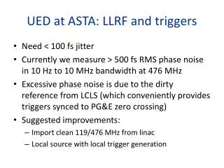
Temporal laser and e-beam overlap 2000 mesh TEM Grid -8 ps -4 ps 0 ps 400 fs step size Steps to find time-zero 1) Fast photodiode D1 and D2 (< 100 ps or 3 cm) 2) Measure the rest of optical path length (~1 cm) 3) time-of-flight of the e-beam (from simulation) 4) Ultrafast plasma lensing effect (<1 ps) 4 ps 8 ps 12 ps L0 16 ps 20 ps 28 ps up to ~50 J/cm2 3 MeV beam L J. R. Dwyer et al., Phil. Trans. R. Soc. A 364, 741 (2006) H. Park et al., RSI 76, 083905 (2005) C. M. Scoby et al., dx.doi.org/10.1016/j.ultramic.2012.07.015
Summary • Pre-operation preparation (checklist, now – August 1st) • Machine operation / e-beam characterization (August 1st - ) • Transverse overlap of laser and e-beam • Temporaloverlap of laser and e-beam • Experiment using samples with ultrafast (100 fs) response Thank you!