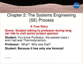
Chapter 2: The Systems Engineering (SE) Process
Chapter 2: The Systems Engineering (SE) Process. A True Story Scene: Student talking to professor during long car ride to visit senior project sponsor Student: You know Professor, the easiest class I ever had was Thermodynamics. Professor: What? Why was that?

Chapter 2: The Systems Engineering (SE) Process
E N D
Presentation Transcript
Chapter 2: The Systems Engineering (SE) Process A True Story Scene: Student talking to professor during long car ride to visit senior project sponsor Student: You know Professor, the easiest class I ever had was Thermodynamics. Professor: What? Why was that? Student:Because it has only one formula!
Notes to the Professor • The same presentation shown here is available in CHAPTER X on the WEBPAGE. • This is a shortened version for Professors at KSC • GOAL: Teach SE in 1-2 weeks • Learning Acceleration Techniques: • Led by the professor, System Engineering is “invented” by the class without it being formally introduced. “An Original Thought Exercise” • The common types of subsystems are introduced • Students apply the single SE formula • Students can see examples of every SE function in Chapter X on the WEBPAGE Your Title Here
The Problem that ??? Process Solves • The problem is: • By what process could be created and operated a “system” (or product) that is complex, requires the skills of different engineering disciplines, is reliable with low risk of failure, with reduced chance of cost overruns and a shortened development time? Your Title Here
Terminology: The Hierarchy and Elements • Elements of a system are not just hardware but can also include software, and can even include people, facilities, policies, documents and databases. • System - an integrated set of elements that accomplish a defined objective. What is to be created. • Subsystem-is a system in its own right, except it normally will not provide a useful function on its own, it must be integrated with other subsystems (or systems) to make a system. • Components are elements that make up a subsystem or system. • Parts are elements on the lowest level of the hierarchy. Your Title Here
Position-Controlled Dish Antenna System • A dish antenna system on earth that receives a radio signal from a satellite, and that will automatically point the dish toward the satellite moving across the horizon. • Motor Control Subsystem - motor, position and velocity sensors, controller, software, wires. (motor is a component) • Structures Subsystem • Communications Subsystem – electronics, dish is a part • Electrical Power Subsystem Your Title Here
Imagine Designing a Part, Component or Subsystem • Imagine you were asked to design a part, component or subsystem, for example a can opener, a mousetrap, a bicycle, an automotive suspension, etc. • Question: What process would you follow? • Answer: The Engineering Design Process (EDP) Your Title Here
The Engineering Design Process (EDP) • Project Definition – meet with stakeholders, define the mission objective(s), understand the problem. • Requirements Definition and Engineering Specifications – carefully and thoughtfully develop requirements that will guide the design creation to follow. Clearly document the requirements and receive stakeholder approval before proceeding. • Conceptual Design – generate ideas, compare using trade studies, models, proof-of-concept prototypes, down select to focus on a meritorious concept in the next step. • Product Design, Fabrication and Test – complete all detailed drawings, make or purchase parts and components, assemble and measure performance. If performance requirements are met, begin manufacturing. • Project Definition -Requirements Definition -Conceptual Design -Product Design -Manufacturing Your Title Here
Now Consider Designing a System Made Up of Many Subsystems • EDP Doesn’t offer much guidance for a complex system made up of many subsystems, although it can be applied to design any single subsystem Your Title Here
Common Subsystem Types • Although quite different products, there are common types of subsystems in satellites, rockets and rovers. Your Title Here
Classroom Discussion #1:What subsystems might be needed for a teleoperated lunar excavator? • Note that: • In order to create a system to meet the mission objective, design teams would eventually be formed, one team for each expected subsystem. • These specialty design teams will be applying the EDP to design their own subsystem. • The teams will also be applying "Concurrent Engineering", where multiple subsystems are being designed simultaneously by different teams, with strong collaboration across boundaries of subsystems and disciplines. "The objective of concurrent engineering is to reduce the produce development cycle time through a better integration of activities and processes" - NASA Systems Engineering Handbook SP-601S. Your Title Here
Concurrent Engineering • Concurrent Engineering leads to more design changes earlier, but fewer total design changes overall
Concurrent Engineering • 80-90% of project cost is “locked-in” at the concept design phase. • Insufficient consideration of alternatives in concept design phase can be an expensive mistake if performance does not meet requirements
Classroom Discussion #2: List all the tasks you think should be performed to make sure that separately designed subsystems, when integrated together, will create a system able to perform the mission? • The instructor should allocate enough time for the class to discuss, and the professor lists the answers on the board. Alternatively, the class may be broken up into teams of 5 students that work together for 15 minutes, and then each team lists their answers on the board. After this exercise, students will hopefully have a good feel for what "Systems Engineering" is, without it having been defined yet! Your Title Here
So Now What is Systems Engineering (SE)? • Systems Engineering (SE) is the engineering process to create a system. It is a structured process based on concurrent engineering and that incorporates the Engineering Design Process. • "Systems Engineering (SE) is a disciplined approach for the definition, implementation, integration and operations of a system (product or service) with the emphasis on the satisfaction of stakeholder functional, physical and operational performance requirements in the intended use environments over its planned life cycle within cost and schedule constraints. Systems Engineering includes the engineering activities and technical management activities related to the above definition considering the interface relationships across all elements of the system, other systems or as a part of a larger system.“ NASA Systems Engineering Handbook SP-601S Your Title Here
The Single Systems Engineering Formula: SE = Vee + 11 SE Functions + Tools Your Title Here
SE = Vee + 11 SE Functions + Tools Your Title Here
The Vee is a Process Model • In each box are the objectives of the Phase. • For each box on left leg apply the 11 SE Functions to achieve the objectives • Process - Move Down Left Leg completing each and every Phase sequentially, then move up the right leg. The right leg is concerned with physical realization (“implementation”). • Pre-Phase A (Concept Studies)- Produce a Broad Spectrum of Ideas (“feasible alternatives”) • Phase A (Concept and Technology Development) - Through trade studies achieve a Single System “Architecture” with requirements • Phase B (Produce a Preliminary Design) - Establish a preliminary design, with subsystem requirements, interfaces, and with technology issues resolved. • Phase C ( Detailed Design ) – detailed design and drawings, purchase or manufacture parts and components, code software. • Phase D (System Assembly, Integration, Test and Launch) Assemble subsystems, integrate subsystems to create systems, test to verify and validate performance, deploy the system. Your Title Here
Vee Chart Features • Left Leg: Formulation Phases are concerned with Decomposition and Definition. Right Leg: Implementation Phases are concerned with Integration and Verification • Decomposition and definition is logically “tearing down” the system to eventually reveal the complete system architectural design. • Proceeding up the right leg, Integration and Verification is equivalent to “building up” the physical system and testing - from the component level to a completed functioning and tested system. • Boxes on the same horizontal level are the same product hierarchy level. Requirements created on the left side “translate” horizontally to requirements for testing during implementation. • The Vee chart is divided by a horizontal dashed line that reveals the responsibility boundary between the systems engineering tasks and the tasks typically performed by the design engineering teams applying the EDP to create a detailed design of a subsystem. Your Title Here
SE = Vee + 11 SE Functions + Tools Your Title Here
Function 1:Mission Objectives • Function 1: Mission Objectives are statement(s) that clearly document the goal(s) and constraint(s) of the mission. Constraints are pre-imposed limitations on the project. The mission objective follows from the stakeholders and their expectations. • Mission Objective for the Apollo 8 Mission • “The overall objective of the mission was to demonstrate command and service module performance in a cislunar (between the Earth and Moon) and lunar-orbit environment, to evaluate crew performance in a lunar-orbit mission, to demonstrate communications and tracking at lunar distances, and to return high-resolution photography of proposed Apollo landing areas and other locations of scientific interest.” Your Title Here
Function 2:Derived Requirements • There are many kinds of requirements, including functional, performance, verification and interface requirements. Requirements are level dependent; they are system (top level), subsystem, or component (bottom level) requirements. Requirements are often expressed as "shall" statements. • “The Thrust Vector Controller shall provide vehicle control about the pitch and yaw axis” [2]. (This is a requirement for the Attitude Control Subsystem) • b. “The ground station shall provide communication between the excavator and the human operator” (This is a requirement for the Ground Station Subsystem) Your Title Here
Function 3:Architectural Design Development • An architectural design (or just an architecture) is a “description of the elements, their interfaces, their logical and physical layout and the analysis of the design to determine expected performance”. It is not a detailed design - that is performed by the subsystem design teams and is not a SE function. It begins as a hierarchy of major subsystems on a block diagram (e.g., an organizational chart in PowerPoint) in Pre-Phase A with only one or two tiers, becoming more detailed by adding more tiers as progress advances through the phases. • The following pictures show development from pre-Phase A thru A and thru B Your Title Here
Function 3: Architectural Design Development Your Title Here
Function 4:Concept of Operations • Concept of Operations(ConOps) is a description of how the system will operate to meet stakeholder expectations. Your Title Here
Function 5:Validate and Verify • Validate and Verifyis another SE function that is ongoing during requirements, architectural design and ConOps formulation in order to guarantee they will lead to a plausible design, and are consistent. In most cases this will be achieved by logical argument. Secondly, validate and verify guide the physical testing in Phase D; to do this the student team should create requirements in Phase B to be able to perform Requirements Verification, System Verification and System Validation in Phase D testing. • Requirements Verification is proving that each requirement is satisfied. • System Verification is assuring that the system is built right. • System Validation is assuring that the right system is built for the intended environment. Your Title Here
Function 6:Interfaces and ICD (Interface Control Document) • Interfaces and ICD (Interface Control Document)Interfaces are mechanical, electrical, thermal and operational boundaries that are between elements of a system. The interfaces appear as the architectural design progresses, by the addition of more and more detail to the subsystems and components. The ICD specifies the mechanical, thermal, electrical, power, command, data, and other interfaces. • Example from the CubeSat Chapter - C&DH System Interface connections: • Confirm antenna release, Antenna release, Power in, Ground, Data in from comm, Data out to Comm, PTT control, VX-2R power control, Decoder/Encoder, Antenna switching control, Temperature sensors (Solar cells, 2 Batteries, 2 Microcontrollers 1 and 2, VX-2R, payload), Voltage sensors (Solar cells, 2 Batteries, 2 Microcontrollers, Payload), Payload data in. Your Title Here
Function 7: Mission Environment • Mission Environment must be communicated, because it does affect the design, and it could include vibration, shock, static loads, acoustics, thermal, radiation, single event effects (SEE) and internal charging, orbital debris, magnetic, and radio frequency (RF) exposure. Chapter 5 described the lunar environment. Your Title Here
Function 8:Technical Resource Budget Tracking • Function 8: Technical Resource Budget Tracking identifies and tracks resource budgets, which can include mass, volume, power, battery, fuel, memory, process usage, data rate, telemetry, commands, data storage, RF links, contamination, alignment, total dose radiation, SEE, surface and internal charging, meteoroid hits, ACS pointing and disturbance and RF exposure. Your Title Here
Function 9: Risk Management • Function 9: Risk Management identifies the risks to safety, performance and the program (cost overruns and schedule delays). Performance and safety risk may be a design consideration, calling for a design change or improvement. The steps of Failure Mode Analysis (FMA) are 1) Seek and identify the risks, 2) Determine their severity and effect of the risk based on coding as shown in the Figure 11, and 3) Develop methods to mitigate the risk. Codes of the severity of a risk range from 1 (non-critical failure) to 4 (entire mission failure). Mitigation can be achieved by providing redundant components, fault tolerant components, and error detection methods. Your Title Here
Function 10: Configuration Management and Documentation • Configuration Management and Documentation is a system for documentation control, access, approval and dissemination. The teams should have an accessible drive on the university computer network to place documents, or something equivalent. Your Title Here
Function 11: System Milestone Reviews and Reports Suggested Format of a Review Report • Title of Review (e.g. SDR, PDR, CDR, ORR) and goals • Project Management: Presentation + report including 1) management structure, 2) cost budget, 3) Gantt Charts (task assignments, schedule of lifecycle with milestones) • System Engineering: 1) the 11 SE functions, 2) SEMP • Subsystem Design Engineering: Technical report on each subsystem • Project Manager summarizes and presents objectives for next Review
Program Manager Project Management Structure Project Manager Systems Engineer EPS Lead ADC Lead Structures Lead Thermal Lead Ground Station Lead COMM Lead C&DH Lead Payload Lead Your Title Here
The Systems Engineer • The function of systems engineering is to “guide the engineering of complex systems” and to form bridges across traditional engineering disciplines that are designing the individual systems elements that must interact with each other. Tasks Include: • Leading the development of the systems architecture • Defining, verifying and validating system requirements, and their flow down the product hierachy • Evaluating design tradeoffs from trade studies • Responsibility for guiding the integration and test phases of the project • Balancing technical risk between systems, failure mode analysis • Defining and assessing interfaces • Providing oversight of verification and validation activities
Project Management – Work Breakdown Structure in Gantt Chart Form Your Title Here
SE = Vee + 11 SE Functions + Tools Your Title Here
National Aeronautics and Space Administration Title Master www.nasa.gov
Slide Master Your Title Here