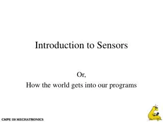
Adding sensors to intersection
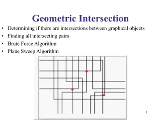
This document outlines the design and algorithms for an advanced traffic control system at a major intersection. It describes the flow chart and state timing diagrams, showcasing how the North/South traffic is managed, with emphasis on the control of East/West signals based on sensor inputs. The system operates using a state table, incorporating sensors to detect vehicle presence and modify signal timings dynamically. Important points include signal timing for green, yellow, and red states along with decision points as represented by diamonds in the algorithm.

Adding sensors to intersection
E N D
Presentation Transcript
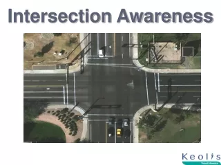
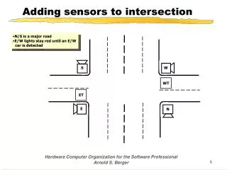
Adding sensors to intersection • N/S is a major road • E/W lights stay red until an E/W • car is detected S W WT ET E N Hardware Computer Organization for the Software Professional Arnold S. Berger
Flow chart for busy intersection • Algorithm: • 1- NS is green and EW is red for • 20 seconds. • 2- If no E/W car is waiting, go to #1 • 3- Else Allow EW traffic to go for • 20 seconds • 4- Go to #1 • KEY POINTS • State of E/W traffic sensors can • modify the behavior of the system • Diamonds represent decision • points in the Algorithm NS GREEN EW RED 20 Seconds NO WT = 1 NS RED EW YELLOW 5 Seconds YES NO YES ET = 1 NS RED EW GREEN 20 Seconds NS YELLOW EW RED 5 Seconds Hardware Computer Organization for the Software Professional Arnold S. Berger
Timing diagram for traffic signal NS RED 1 0 NS YELLOW 1 0 1 0 NS GREEN EW RED 1 0 EW YELLOW 1 0 1 0 EW GREEN 0 5 10 15 20 25 30 35 40 45 50 Time, seconds Hardware Computer Organization for the Software Professional Arnold S. Berger
Timing diagram as a vector set NS GREEN NS YELLOW NS RED EW GREEN EW YELLOW EW RED Hexadecimal State Time 0 5 10 15 20 25 30 35 40 45 50 0 0 1 1 0 0 0C 0 0 1 1 0 0 0C 0 0 1 1 0 0 0C 0 0 1 1 0 0 0C 0 1 0 1 0 0 14 1 0 0 0 0 1 21 1 0 0 0 0 1 21 1 0 0 0 0 1 21 1 0 0 0 0 1 21 1 0 0 0 1 0 22 0 0 1 1 0 0 0C Hardware Computer Organization for the Software Professional Arnold S. Berger
Designing the traffic controller NS RED EW YELLOW NS RED EW GREEN NS RED EW GREEN NS RED EW GREEN NS RED EW GREEN NS GREEN EW RED NS GREEN EW RED NS GREEN EW RED NS GREEN EW RED NS GREEN EW RED State variables 0000 0H 0001 1H 0010 2H 0011 3H 0100 4H 0101 5H 0110 6H 0111 7H 1000 8H 1001 9H Flow chart Redraw so that every state is 5 seconds long NS RED EW GREEN 20 Seconds NS RED EW YELLOW 5 Seconds NS GREEN EW RED 20 Seconds NS YELLOW EW RED 5 Seconds Hardware Computer Organization for the Software Professional Arnold S. Berger
D flip-flop synchronizes states The output values in the register is the address of the memory cell for the data that determines the next state of the outputs after the clock arrives NSG NSY NSR EWG EWY EWR A0 D0 Q0 D0 A1 D1 Q1 D1 State Variable provides the input A2 D2 Q2 D2 A3 D3 Q3 D3 CLK D4 D REGISTER D5 16 x 6 Memory Array Clock frequency = 0.2 Hz Hardware Computer Organization for the Software Professional Arnold S. Berger
Traffic controller state table State Outputs ROM Address ROM Contents Q3 Q2 Q1 Q0 D5 D4 D3 D2 D1 D0 0 0 0 0 0H 0 0 1 1 0 0 0CH 0 0 0 1 1H 0 0 1 1 0 0 0CH 0 0 1 0 2H 0 0 1 1 0 0 0CH 0 0 1 1 3H 0 0 1 1 0 0 0CH 0 1 0 0 4H 0 1 0 1 0 0 14H 0 1 0 1 5H 1 0 0 0 0 1 21H 0 1 1 0 6H 1 0 0 0 0 1 21H 0 1 1 1 7H 1 0 0 0 0 1 21H 1 0 0 0 8H 1 0 0 0 0 1 21H 1 0 0 1 9H 1 0 0 0 1 0 22H 1 0 1 0 AH X X X X X X Don’t Care 1 0 1 1 BH X X X X X X Don’t Care 1 1 0 0 CH X X X X X X Don’t Care 1 1 0 1 DH X X X X X X Don’t Care 1 1 1 0 EH X X X X X X Don’t Care 1 1 1 1 FH X X X X X X Don’t Care Hardware Computer Organization for the Software Professional Arnold S. Berger
State sequencing Use the ROM contents to sequence from one state to the next NSG NSY NSR EWG EWY EWR D0 D1 D2 D3 D4 D5 D6 D7 D8 D9 A0 Q0 D0 A1 Q1 D1 A2 Q2 D2 A3 Q3 D3 CLK D REGISTER 16 x 10 Memory Array Clock frequency = 0.2 Hz Hardware Computer Organization for the Software Professional Arnold S. Berger
New state table with sequencing Next State Outputs Current State ROM Address ROM Contents D9 D8 D7 D6 D5 D4 D3 D2 D1 D0 0H 0 0 0 1 0 0 1 1 0 0 04CH 1H 0 0 1 0 0 0 1 1 0 0 08CH 2H 0 0 1 1 0 0 1 1 0 0 0CCH 3H 0 1 0 0 0 0 1 1 0 0 10CH 4H 0 1 0 1 0 1 0 1 0 0 154H 5H 0 1 1 0 1 0 0 0 0 1 1A1H 6H 0 1 1 1 1 0 0 0 0 1 1E1H 7H 1 0 0 0 1 0 0 0 0 1 221H 8H 1 0 0 1 1 0 0 0 0 1 261H 9H 0 0 0 0 1 0 0 0 1 0 022H AH X X X X X X X X X X Don’t Care BH X X X X X X X X X X Don’t Care CH X X X X X X X X X X Don’t Care DH X X X X X X X X X X Don’t Care EH X X X X X X X X X X Don’t Care FH X X X X X X X X X X Don’t Care Hardware Computer Organization for the Software Professional Arnold S. Berger
Adding inputs NSR EWG NSR EWG NSR EWG NSR EWG NSG EWR NSY EWR NSG EWR NSG EWR NSG EWR NSR EWY 0H 1H 2H 3H NS GREEN EW RED 20 Seconds NO NO WT WT = 1 YES 4H 5H ET NS RED EW YELLOW 5 Seconds YES YES NO YES ET = 1 NS RED EW GREEN 20 Seconds NS YELLOW EW RED 5 Seconds 6H 7H 9H 8H Hardware Computer Organization for the Software Professional Arnold S. Berger
Traffic light controller with inputs ET D4 D5 Q4 Q5 A0 WT A1 NSG NSY NSR EWG EWY EWR D0 D1 D2 D3 D4 D5 D6 D7 D8 D9 Q0 D0 A2 A3 Q1 D1 Q2 A4 A5 D2 Q3 D3 CLK D REGISTER 64 x 10 Memory Array Clock frequency = 0.2 Hz Hardware Computer Organization for the Software Professional Arnold S. Berger
Abbreviated ROM Contents State WT ET Next State Outputs A5 A4 A3 A2 A1 A0 D9 D8 D7 D6 D5 D4 D3 D2 D1 D0 0 0 0 0 X X 0 0 0 1 1 0 0 0 0 1 0 0 0 1 X X 0 0 1 0 1 0 0 0 0 1 0 0 1 0 X X 0 0 1 1 1 0 0 0 0 1 0 0 1 1 0 0 0 0 0 0 1 0 0 0 0 1 0 0 1 1 0 1 0 1 0 0 1 0 0 0 0 1 0 0 1 1 1 0 0 1 0 0 1 0 0 0 0 1 0 0 1 1 1 1 0 1 0 0 1 0 0 0 0 1 0 1 0 0 X X 0 1 0 1 1 0 0 0 1 0 0 1 0 1 X X 0 1 1 0 0 0 1 1 0 0 0 1 1 0 X X 0 1 1 1 0 0 1 1 0 0 0 1 1 1 X X 1 0 0 0 0 0 1 1 0 0 1 0 0 0 X X 1 0 0 1 0 1 0 1 0 0 1 0 0 1 X X 0 0 0 0 0 1 0 1 0 0 1 0 1 0 X X 0 0 0 0 0 0 0 0 0 0 1 0 1 1 X X 0 0 0 0 0 0 0 0 0 0 1 1 0 0 X X 0 0 0 0 0 0 0 0 0 0 1 1 0 1 X X 0 0 0 0 0 0 0 0 0 0 1 1 1 0 X X 0 0 0 0 0 0 0 0 0 0 1 1 1 1 X X 0 0 0 0 0 0 0 0 0 0 Hardware Computer Organization for the Software Professional Arnold S. Berger
Simplified Schematic Diagram Hardware Computer Organization for the Software Professional Arnold S. Berger
Sequential Digital Machine External Inputs OUTPUTS Current State Microsequencer or ROM State Flip- Flops Clock NEXT STATE Hardware Computer Organization for the Software Professional Arnold S. Berger
Adding two numbers together • Assume that we want to add two 4-bit numbers together • We assume that we have a 4-bit full adder made up of 4, 1-bit full adder circuits connected as shown below: 3 2 1 0 Cout Cin = 0 DB3 DB2 DB1 DB0 A3 B3 A2 B2 A1 B1 A0 B0 Hardware Computer Organization for the Software Professional Arnold S. Berger
State machine sequence • In this example it would require 5 clock cycles to perform this addition Add A0..A3 to B0..B3 Connect A0..A3 to Adder Connect B0..B3 to Adder Save state of Cout Store SUM Register holding A0..A3 Cout 4-bit full adder Register holding A0..A3 Register holding B0..B3 Hardware Computer Organization for the Software Professional Arnold S. Berger
Glimpse at processor design • The ASM is the basis for almost all of today’s computing engines • The Instruction Set Architecture is determined by the microcode stored in a ROM section of the processor • The processor sequences through a series of states determined by: • The instruction • Contents of internal registers • Results of arithmetic or logical operations • Type of memory addressing mode being used • Asynchronous internal or external events (interrupts) Compute Operand 2 Address Fetch Operand 1 Compute Operand 1 Address Fetch Instruction Decode Instruction Write back Results Fetch Operand 2 Advance Program Counter Perform Operation Hardware Computer Organization for the Software Professional Arnold S. Berger