Network RC Car
Learn how to utilize a microprocessor to modify camera output signals for precise control of an RC car. Explore pulse width modulation, clock frequency adjustments, setting duty cycles, and utilizing capture timers for enhanced control.


Network RC Car
E N D
Presentation Transcript
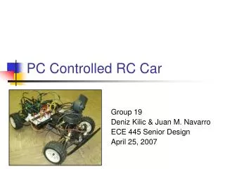
Network RC Car Seth Schwiethale James Crosetto James Ellison
Car’s Input • square pulse of 1.0-2.0 ms, repeats every 20 ms • It is the same for both steering and acceleration • width of the pulse determines the direction/speed w/ 1.5 ms as the nominal center • the amplitude of the pulse is from the reference level of the Vcc (5v)
Camera’s Output • 1 “alarm” output • max activation is 100 times/sec (increments of 10 ms)
The Problem • Camera’s output can’t produce a 20ms PWM signal that is highbetween 1-2ms • Car cannot be driven by Camera directly • need something that modifies the output signal of the camera so it can be used by the car
The Solution • Using a microprocessor (MC9S12DP256) • has a clock signal rate of 24MHz • has registers for a Pulse Width Modulator and an Enhanced Capture Timer • Signal from the camera can be varied between 10-110ms for speed and 120-220ms for steering
Pulse Width Modulation camera’s output microprocessor car’s input
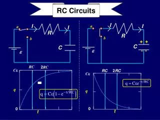
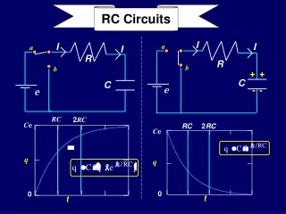
Pulse Width Modulator • used to create correct output signal • uses CPU clock signal to generate signal lengths • current signal is 24MHz and we need a 50Hz (20ms) signal (Factor of 480000!)
Determining the Output Signal • Initializing the Pulse Width Modulator
Modifying the Clock Frequency • The pulse width modulator uses registers to decrease the frequency of the clock signal before it is used as an output signal • Two output signals can be generated from the clock signal Allows for finer control of signal
Setting the Period • The periods of both SA and SB need to be 20ms
Setting the Duty Cycle • The duty cycle (the part of the PWM signal that is high) needs to be 1-2ms in length • Initialized to 1.5 ms Notice the difference!
Enhance Capture Timer • Used to trigger interrupts • Set up to trigger an interrupt every time a signal goes high or low on an input port (TCTL4 and TIE)
Counting • Timer Register (TCNT) is incremented every clock cycle (24MHz clock = 24 million times per second) • Clock slowed to 187.5 KHz • TCNT is 16-bit register (0-65535) • Overflows about every 1/3 second (65535/187500) • Never overflows more than once per input signal from camera