CLK
Department of Electrical and Computer Engineering ECE 415/ECE 416 SENIOR DESIGN PROJECT 2007 College of Engineering - University of Massachusetts Amherst. Portable Harmonic Radar Transceiver. Team Members: Mikeoll Echeverria, Maria Gomes, Juan Lopez Faculty Advisor: Marinos Vouvakis.

CLK
E N D
Presentation Transcript
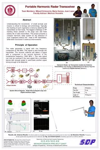
Department of Electrical and Computer Engineering ECE 415/ECE 416 SENIOR DESIGN PROJECT 2007 College of Engineering - University of Massachusetts Amherst Portable Harmonic Radar Transceiver Team Members: Mikeoll Echeverria, Maria Gomes, Juan Lopez Faculty Advisor: Marinos Vouvakis Abstract Understanding the movements of small animals and insects is critical to biology and entomology. Typically the tracking of such organisms is done by attaching RF transmitters at their body. The biggest challenge in RF tracking these animals is the large size and finite battery life of radio transmitters. This project presents a compact harmonic radar system for the detection of such organisms without the need of RF transmitters, while been functional in cluterous environments. (b) Principle of Operation The radar generates a signal with one frequency component at 780 MHz. This signal is sent through the transmitter. The receiver antenna will detect a signal with a component in the second harmonic of the fundamental frequency (1560 MHz ). This new signal can only be received if the sent signal hits a nonlinear device with enough power to send back another signal strong enough to be detected. (c) (a) VCO Attenuator Amp Harmonic Radar: (a) Transceiver module (b) Antenna: Transmitting (large dipoles) and Receiving (small dipoles) Yiagi-Uda antennas (c) Digital Interface (detector ) TX Signal 780MHz VCO CLK DC Signal Power Detector LNA LNA LNA Technical Characteristics RX Signal 1560 MHz System Block Diagram: Radar Block Diagram (top) and Digital interface (right) Microcontroller Target Detected Target Detected LED LED Transmitter Receiver Tag LED Transmitter (b) No tag (d) (c) (a) Receiver Results: (a) Antenna Results: 3D antenna patterns and graphs of transmitting and receiving antenna return loss (b) Detection Results: Frequency domain graphs when tag detected and not detected (c) Tag (d) Overall System: illustrating signal with and without detection Acknowledgments: We would like to thank: Fernando Rodriguez-Morales, Pei-Sang Tsai, Justin Creticos, Eric Marklein, Ana Sastre, Professor Paul Siqueira, Professor Dennis Goeckel, Richard Winn , Francis Caron, Keith Shimeld, and Professor Marinos Vouvakis. You made this project possible .