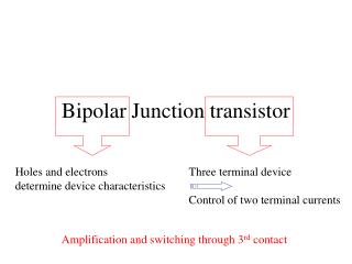
Bipolar transistor
C. B. E. Bipolar transistor. BJT – Bipolar Junction Transistor. Dua Type BJT Transistor:. npn. pnp. n. p. n. p. n. p. E. C. E. C. Cross Section. C. Cross Section. C. B. B. B. B. Symbol. Symbol. E. E. Collector doping is usually ~ 10 6


Bipolar transistor
E N D
Presentation Transcript
C B E Bipolar transistor
BJT – Bipolar Junction Transistor Dua Type BJT Transistor: npn pnp n p n p n p E C E C Cross Section C Cross Section C B B B B Symbol Symbol E E • Collector doping is usually ~ 106 • Base doping is slightly higher ~ 107 – 108 • Emitter doping is much higher ~ 1015
Rumusan Dasar BJT IE IC IE IC - VCE + + VEC - E C E C - - + + VBE VBC IB VEB VCB IB + + - - B B npn IE = IB + IC VCE = -VBC + VBE pnp IE = IB + IC VEC = VEB - VCB
DC and DC = Arus penguatan Common-emitter = Arus penguatan Common-base = IC = IC IB IE Hubungan antara dua parameters tersebut adalah: = = + 1 1 -
BJT Example Konfigurasi Common-Base Transistor NPN • Diketahui : IB = 50 A , IC = 1 mA • Hitung : IE , , and • Penyelesaian: • IE = IB + IC = 0.05 mA + 1 mA = 1.05 mA • = IC / IB = 1 mA / 0.05 mA = 20 = IC / IE = 1 mA / 1.05 mA = 0.95238 Juga dapat dicari dengan dengan rumus sebagai berikut. = = 20 = 0.95238 + 1 21 C IC VCB + _ IB B VBE IE + _ E
Curve TransconductanceBJT Transistor Tipe NPN Arus Collector : IC = IESeVBE/VT Transconductance: (slope of the curve) gm = IC / VBE IES = Arus saturasi terbalik dari B-E Junction. VT = kT/q = 26 mV (@ T=300K) = Coefisien emisi biasanya ~1 IC 8 mA 6 mA 4 mA 2 mA VBE 0.7 V
Modes of Operation Active: • Posisi terbaik pada daerah operasi • Beroperasi sebagai penguat Saturation: • Transistor berada sebagaimana pada posisi short circuit. Cutoff: • Arus transistor nol • Transistor yang edial sebagaimana posisi saklar terbuka * Note: There is also a mode of operation called inverse active, but it is rarely used.
TigaTypesdari Bias BJT Bias transistor adalah kondisi tegangan dimana transistor tersebut bisa melakukan operasi (kerja). Bias Common-Base (CB) : input = VEB & IE output = VCB & IC Bias Common-Emitter (CE): input = VBE & IB output = VCE & IC Bias Common-Collector (CC): input = VBC & IB output = VEC & IE
Common-Base Although the Common-Base configuration is not the most common biasing type, it is often helpful in the understanding of how the BJT works. Emitter-Current Curves IC Active Region IE Saturation Region Cutoff IE = 0 VCB
VCE IC IE C E VCB VBE IB + _ + _ B VCB VBE Common-Base Circuit Diagram: NPN Transistor The Table Below lists assumptions that can be made for the attributes of the common-base biased circuit in the different regions of operation. Given for a Silicon NPN transistor.
Common-Emitter Circuit Diagram Collector-Current Curves VCE IC IC VCC + _ Active Region IB IB VCE Saturation Region Cutoff Region IB = 0
Common-Collector Emitter-Current Curves IE The Common-Collector biasing circuit is basically equivalent to the common-emitter biased circuit except instead of looking at IC as a function of VCE and IB we are looking at IE. Also, since ~ 1, and = IC/IE that means IC~IE Active Region IB VCE Saturation Region Cutoff Region IB = 0
Eber-Moll BJT Model The Eber-Moll Model for BJTs is fairly complex, but it is valid in all regions of BJT operation. The circuit diagram below shows all the components of the Eber-Moll Model: IE IC E C RIC RIE IF IR IB B
Eber-Moll BJT Model R = Common-base current gain (in forward active mode) F = Common-base current gain (in inverse active mode) IES = Reverse-Saturation Current of B-E Junction ICS = Reverse-Saturation Current of B-C Junction IC = FIF – IR IB = IE - IC IE = IF - RIR IF = IES [exp(qVBE/kT) – 1] IR = IC [exp(qVBC/kT) – 1] If IES & ICS are not given, they can be determined using various BJT parameters.
Small Signal BJT Equivalent Circuit The small-signal model can be used when the BJT is in the active region. The small-signal active-region model for a CB circuit is shown below: iB iC B C r iB r = ( + 1) * VT IE iE E @ = 1 and T = 25C r = ( + 1) * 0.026 IE Recall: = IC / IB
The Early Effect (Early Voltage) IC Note: Common-Emitter Configuration IB -VA VCE Green = Ideal IC Orange = Actual IC (IC’) IC’ = IC VCE + 1 VA
Early Effect Example Given: The common-emitter circuit below with IB = 25A, VCC = 15V, = 100 and VA = 80. Find: a) The ideal collector current b) The actual collector current Circuit Diagram VCE IC • = 100 = IC/IB a) IC = 100 * IB = 100 * (25x10-6 A) IC = 2.5 mA + _ VCC IB b) IC’ = IC VCE + 1 = 2.5x10⁻³ 15 + 1 = 2.96 mA VA 80 IC’ = 2.96 mA
Breakdown Voltage The maximum voltage that the BJT can withstand. BVCEO = The breakdown voltage for a common-emitter biased circuit. This breakdown voltage usually ranges from ~20-1000 Volts. BVCBO = The breakdown voltage for a common-base biased circuit. This breakdown voltage is usually much higher than BVCEO and has a minimum value of ~60 Volts. • Breakdown Voltage is Determined By: • The Base Width • Material Being Used • Doping Levels • Biasing Voltage
Sources Dailey, Denton. Electronic Devices and Circuits, Discrete and Integrated. Prentice Hall, New Jersey: 2001. (pp 84-153) 1 Figure 3.7, Transconductance curve for a typical npn transistor, pg 90. Liou, J.J. and Yuan, J.S. Semiconductor Device Physics and Simulation. Plenum Press, New York: 1998. Neamen, Donald. Semiconductor Physics & Devices. Basic Principles. McGraw-Hill, Boston: 1997. (pp 351-409) Web Sites http://www.infoplease.com/ce6/sci/A0861609.html