Bipolar Junction Transistor (BJT)
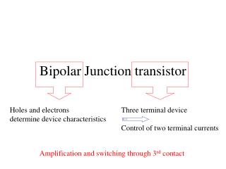
Bipolar Junction Transistor (BJT). OUTLINE. General considerations Structure Operation in active mode Large-signal model and I-V characteristics Reading: Chapter 4.1-4.4.2. Voltage-Dependent Current Source. A voltage-dependent current source can act as an amplifier.


Bipolar Junction Transistor (BJT)
E N D
Presentation Transcript
OUTLINE • General considerations • Structure • Operation in active mode • Large-signal model and I-V characteristics Reading: Chapter 4.1-4.4.2
Voltage-Dependent Current Source A voltage-dependent current source can act as an amplifier. If KRL is greater than 1, then the signal is amplified.
Voltage-Dependent Current Source with Input Resistance The magnitude of amplification is independent of the input resistance rin.
Exponential Voltage-Dependent Current Source Ideally, a bipolar junction transistor (BJT) can be modeled as a three-terminal exponential voltage-dependent current source:
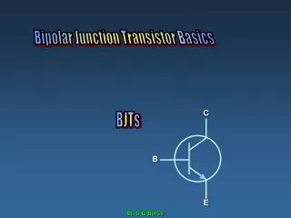
BJT Structure and Circuit Symbol A bipolar junction transistor consists of 2 PN junctions that form a sandwich of three doped semiconductor regions. The outer two regions are doped the same type; the middle region is doped the opposite type.
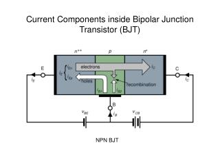
NPN BJT Operation (Qualitative) current gain: In the forward active mode of operation: The collector junction is reverse biased. The emitter junction is forward biased.
Base Current • The base current consists of two components: • Injection of holes into the emitter, and • Recombination of holes with electrons injected from the emitter.
BJT Design • Important features of a well-designed BJT (large b ): • Injected minority carriers do not recombine in the quasi-neutral base region. Make base width small compared to minority carrier diffusion length LB • Emitter current is comprised almost entirely of carriers injected into the base (rather than carriers injected into the emitter). Dope emitter more heavily than the base
Carrier Transport in the Base Region • Since the width of the quasi-neutral base region (WB = x2-x1) is much smaller than the minority-carrier diffusion length, very few of the carriers injected (from the emitter) into the base recombine before they reach the collector-junction depletion region. Minority-carrier diffusion current is ~constant in the quasi-neutral base • The minority-carrier concentration at the edges of the collector-junction depletion region are ~0.
Diffusion Example Redux • Linear concentration profile • constant diffusion current Non-linear concentration profile varying diffusion current
Collector Current The equation above shows that the BJT is indeed a voltage-dependent current source; thus it can be used as an amplifier.
Emitter Current Applying Kirchhoff’s Current Law to the BJT, we can easily find the emitter current.
Parallel Combination of Transistors When two transistors are connected in parallel and have the same terminal voltages, they can be considered as a single transistor with twice the emitter area.
Simple BJT Amplifier Configuration Although the BJT converts an input voltage signal to an output current signal, an (amplified) output voltage signal can be obtained by connecting a “load” resistor (with resistance RL) at the output and allowing the controlled current to pass through it.
BJT as a Constant Current Source Ideally, the collector current does not depend on the collector-to-emitter voltage. This property allows the BJT to behave as a constant current source when its base-to-emitter voltage is fixed.
Constraint on Load Resistance • If RL is too large, then VX can drop to below ~0.8V so that the collector junction is forward biased. In this case, the BJT is no longer operating in the active mode, and so There exists a maximum tolerable load resistance.
BJT Large Signal Model A diode is placed between the base and emitter terminals, and a voltage-controlled current source is placed between the collector and emitter terminals.
BJT vs. Back-to-Back Diodes Figure (b) presents a wrong way of modeling the BJT.