Download
1 / 1
20 likes | 193 Vues
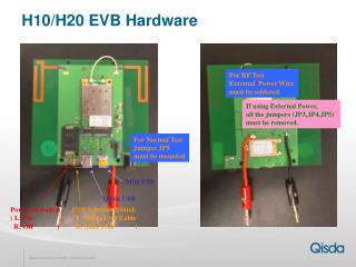
This guide provides essential information on the hardware configuration for RF testing using external power. It details the requirement to solder the external power wire and emphasizes the importance of removing all jumpers (JP3, JP4, JP5) when external power is applied. For normal testing conditions, jumper JP5 must be mounted. Additionally, instructions are given for the Mini USB power switch (Qisda) and the selection switch for USB power sources, ensuring proper setup and operation.

E N D
H10/H20 EVB Hardware For RF Test External Power Wire must be soldered. If using External Power, all the jumpers (JP3,JP4,JP5) must be removed. For Normal Test Jumper JP5 must be mounted Mini USB Qisda USB Power on Switch( L: On R: Off ) USB Selection Switch( L: Qisda USB Cable R: Mini USB )